
Page 36 - MetalForming January 2016
P. 36
The Science of Forming
By Stuart Keeler
Stretch, Bend & Draw: Different Forming Modes?
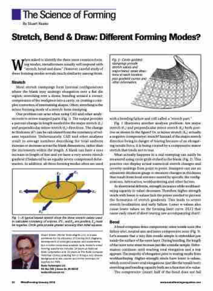
Fig. 2—Circle-gridded stampings provide stretch values and major/minor strain direc- tions at each location, plus gradient curves and other information.
When asked to identify the three most common form- ing modes, metalformers usually will respond with “stretch, bend and draw.” However, careful study of these forming modes reveals much similarity among them.
Stretch
Most stretch stampings form internal configurations where the blank may undergo elongation over a flat die region; stretching over a dome; bending around a corner; compression of the workpiece into a cavity; or creating a com- plex contortion of intertwining shapes. Often, stretching is the minor forming mode of a stretch-form stamping.
One problem can arise when using CAD and other analy-
sis tools to review stamped parts (Fig. 1). The output provides
with a bending failure and still called a “stretch part.”
a percent change in length needed for the major stretch (Ԑ ) 1
Fig. 1 illustrates another analysis problem: Are major
and perpendicular minor stretch (Ԑ ) directions. The change stretch (Ԑ ) and perpendicular minor stretch (Ԑ ) both posi- 212
3
in thickness (Ԑ ) can be calculated from the constancy of vol-
ume equations. Unfortunately, CAD and other analyses result in average numbers describing the total uniform increase or decrease across the blank dimensions, rather than the increments within the length. A blank can have a zero increase in length of line and yet have a very severe stretch gradient if balanced by an equally severe compressed defor- mation. In addition, all three forming modes often are used
tive as shown in the figure? Or, is minor stretch (Ԑ ) actually 2
a negative (compressive) stretch? Instead of the major stretch direction being in danger of tearing because of an elongat- ing tensile force, it is being created by a compressive minor stretch that tends not to tear.
What actually happens in a real stamping can easily be measured using circle grids etched in the blank (Fig. 2). This practice can display actual numerical stretch changes and severity rankings from point to point. Stampers can use an ultrasonic thickness gauge to measure changes in thickness that result from local stresses caused by specific die config- urations, lubrication, workhardening and other factors.
As sheetmetal deforms, strength increases while workhard- ening capacity (n-value) decreases. Therefore, higher-strength steels with lower n-values lack the power needed to prevent the formation of stretch gradients. This leads to severe stretch localization and early failure. Lower n-values also cause lower values on the forming-limit curve (FLC) that cause early onset of sheet tearing (see accompanying chart).
Bend
A bend comprises three components: outer tensile zone (the failure site), neutral axis and inner compressive zone (Fig. 3). Let’s assume that a very thin tensile sample is embedded just inside the surface of the outer layer. During bending, the length of the outer zone must increase just like a tensile sample. Defor- mation continues until reaching total elongation and a tear appears. The majority of elongation prior to tearing results from workhardening. Higher-strength steels have lower n-values, which control lower total elongations (just like the tensile test); stretching and bending capacity both are a function of n-value.
The compressive (inner) half of the bend does not fail
1
1
2
3
2
to calculate constancy of volume. If Ԑ and Ԑ are positive, Ԑ must 1 2 3
Fig. 1—A typical biaxial stretch show the three stretch values used
be negative. Circle grids provide greater accuracy than initial squares.
Stuart Keeler (Keeler Technologies LLC) is known worldwide for his discovery of forming limit diagrams, development of circle-grid analysis and implementa- tion of other press-shop analysis tools. Keeler’s metal- forming experience includes 24 years at National Steel Corporation and 12 years at The Budd Company Technical Center, enabling him to bring a very diverse background to this column and to the seminars he teaches for PMA.
Keeler Technologies LLC
P.O. Box 283 | Grosse Ile, MI 48138 keeltech@comcast.net
34 MetalForming/January 2016
www.metalformingmagazine.com
