
Page 38 - MetalForming January 2016
P. 38
Tooling by Design
By Peter Ulintz
Improving Punch Life
An important requirement of any die operation is the proper align- ment between all of the working components. In stamping operations, accurate alignment is necessary to maintain proper clearances between punch and die steels.
Cutting, punching and trimming operations require cutting clearances that must be held within close limits. Because many stamping
features are not symmet- rical or totally round, cut- ting clearance usually is measured at one side of the cutting profile and specified as a ‘per-side’ clearance. The amount of clearance applied and the sharpness of the cutting steels all have direct effects on the quality of the sheared edges.
When cutting clear-
ances are small, press and die align- ment become critical. If this alignment is not maintained, the punch and die details may contact each other, dam- aging the cutting edges. Also, high strip- ping and frictional forces acting between the work materials and tooling surfaces will increase the tendency for chipping and wear.
Peter Ulintz has worked in the metal stamping and tool and die industry since 1978. His back- ground includes tool and die making, tool engi- neering, process design, engineering manage- ment and advanced product development. As an educator and technical
presenter, Peter speaks at PMA national seminars, regional roundtables, international conferences, and college and university programs. He also pro- vides onsite training and consultations to the met- alforming industry.
Peter Ulintz
Technical Director, PMA, pulintz@pma.org
When punches require additional chipping and wear resistance, a powder metallurgy (P/M) tool steel may be the solution. P/M tool steels have unique microstructures containing small metal carbides uniformly dispersed in the steel matrix. P/M tool-steel materials are more costly but often prove more economical due to their low wear rate.
Larger cutting clearances make
break without warning.
The best way to protect dies from
damage is to ensure that nothing is physically out of place during a press cycle. This involves mounting sensors in the tooling and equipping the press with a controller to interpret the signals from these devices.
Sensors in stamping dies are proven to reduce the potential for die damage by accurately detecting strip or part positioning, part orientation, feature locations, part presence
and part ejection. Proper sensor selec-
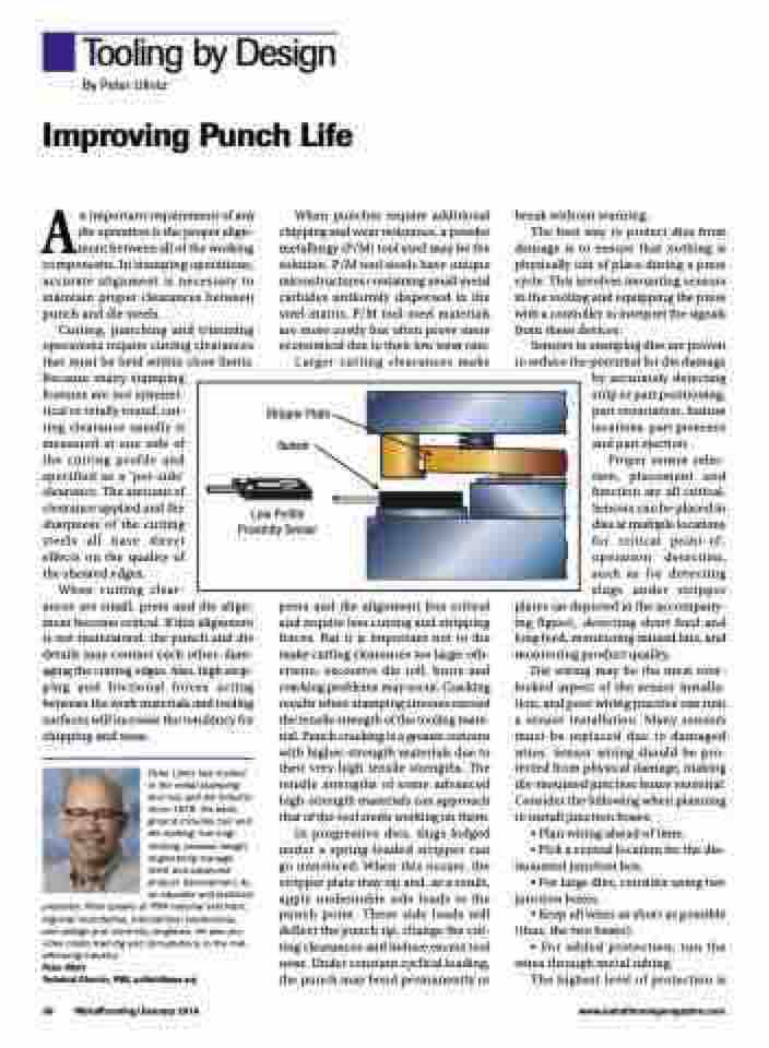
tion, placement and function are all critical. Sensors can be placed in dies at multiple locations for critical point-of- operation detection, such as for detecting slugs under stripper
plates (as depicted in the accompany- ing figure), detecting short feed and long feed, monitoring missed hits, and monitoring product quality.
Die wiring may be the most over- looked aspect of the sensor installa- tion, and poor wiring practice can ruin a sensor installation. Many sensors must be replaced due to damaged wires. Sensor wiring should be pro- tected from physical damage, making die-mounted junction boxes essential. Consider the following when planning to install junction boxes:
• Plan wiring ahead of time.
• Pick a central location for the die- mounted junction box.
• For large dies, consider using two junction boxes.
• Keep all wires as short as possible (thus, the two boxes).
• For added protection, run the wires through metal tubing.
The highest level of protection is
Stripper Plate Sensor
Low Profile Proximity Sensor
press and die alignment less critical and require less cutting and stripping forces. But it is important not to the make cutting clearances too large; oth- erwise, excessive die roll, burrs and cracking problems may occur. Cracking results when stamping stresses exceed the tensile strength of the tooling mate- rial. Punch cracking is a greater concern with higher-strength materials due to their very high tensile strengths. The tensile strengths of some advanced high-strength materials can approach that of the tool steels working on them.
In progressive dies, slugs lodged under a spring-loaded stripper can go unnoticed. When this occurs, the stripper plate may tip and, as a result, apply undesirable side loads to the punch point. These side loads will deflect the punch tip, change the cut- ting clearances and induce excess tool wear. Under constant cyclical loading, the punch may bend permanently or
36 MetalForming/January 2016
www.metalformingmagazine.com
