
Page 27 - MetalForming January 2015
P. 27
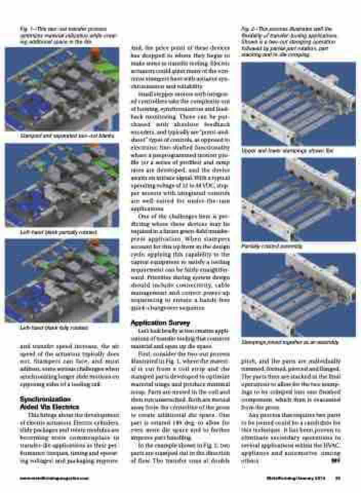
Fig. 2—This process illustrates well the flexibility of transfer-tooling applications. Shown is a two-out stamping operation followed by partial part rotation, part stacking and in-die crimping.
  Upper and lower stampings shown flat.
  Partially rotated assembly.
  Fig. 1—This two-out transfer process optimizes material utilization while creat- ing additional space in the die.
  Stamped and separated two-out blanks.
  Left-hand blank partially rotated.
  Left-hand blank fully rotated.
and transfer speed increase, the air speed of the actuators typically does not. Stampers can face, and must address, some serious challenges when synchronizing longer slide motions on opposing sides of a tooling rail.
Synchronization Aided Via Electrics
This brings about the development of electric actuators. Electric cylinders, slide packages and rotate modules are becoming more commonplace in transfer-die applications as their per- formance (torques, timing and operat- ing voltages) and packaging improve.
And, the price point of these devices has dropped to where they begin to make sense in transfer tooling. Electric actuators could quiet many of the con- cerns stampers have with actuator syn- chronization and reliability.
Small stepper motors with integrat- ed controllers take the complexity out of homing, synchronization and feed- back monitoring. These can be pur- chased with absolute feedback encoders, and typically are “point-and- shoot” types of controls, as opposed to electronic line-shafted functionality where a preprogrammed motion pro- file (or a series of profiles) and ramp rates are developed, and the device awaits an initiate signal. With a typical operating voltage of 12 to 48 VDC, step- per motors with integrated controls are well-suited for under-the-ram applications.
One of the challenges here is pre- dicting where these devices may be required in a future green-field transfer- press application. When stampers account for this up front in the design cycle, applying this capability to the capital equipment to satisfy a tooling requirement can be fairly straightfor- ward. Priorities during system design should include connectivity, cable management and correct power-up sequencing to ensure a hands-free quick-changeover sequence.
Application Survey
Let’s look briefly at two creative appli- cations of transfer tooling that conserve material and open up die space.
First, consider the two-out process illustrated in Fig. 1, where the materi- al is cut from a coil strip and the stamped parts developed to optimize material usage and produce minimal scrap. Parts are nested in the coil and then run unattached. Both are moved away from the centerline of the press to create additional die space. One part is rotated 180 deg. to allow for even more die space and to further improve part handling.
In the example shown in Fig. 2, two parts are stamped out in the direction of flow. The transfer runs at double
Stampings joined together as an assembly.
pitch, and the parts are individually trimmed, formed, pierced and flanged. The parts then are stacked in the final operations to allow for the two stamp- ings to be crimped into one finished component, which then is evacuated from the press.
Any process that requires two parts to be joined could be a candidate for this technique. It has been proven to eliminate secondary operations in several applications within the HVAC, appliance and automotive, among others. MF
www.metalformingmagazine.com
MetalForming/January 2015 25
