


Lastly, Photo C illustrates a traveling-gantry press designed to straighten large-diameter shafts. Its gantry moves only in the X axis to drive over the workpiece, and the main cylinder provides Z-axis movement downward to engage the shaft. All work remains centered under the main ram and the gantry moves over the area to be straightened. Typically, this style of press allows the gantry to move all of the to one end of the press bed in order to load the shafts from an overhead crane. The operator then drives the gantry nose tool over the high spot to perform the straightening process.
Control is the Key
With the proper press selected for the application, the metalformer then turns its attention to gaining complete control over ram movement while applying tonnage to the shaft. Less control may require more hits. State-of-the-art press controls allow operator to dial-in ram depth in increments of 0.001 in.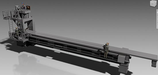
Photo C: The gantry of this traveling-gantry straightening press, designed for large shaft applications, moves only in the X axis to drive over the workpiece. All work remains centered under the main ram.
The control depicted in Photo D, installed on a moveable-gantry press, allows the operator to view actual main-ram position and then input the desired pressing depth in increments of 0.001 in. Included control features:
1) Aux Power Unit supplies the lift and carriage assemblies. This unit finds use when performing shaft work, and can be shut off during plate or weldment work.
2) Lift Assy Up/Down selector switch moves the live centers on which the shaft is mounted.
3) Carriage Up/Down selector switch lifts and lowers the carriage assemblies, to rotate the part and find its high spot.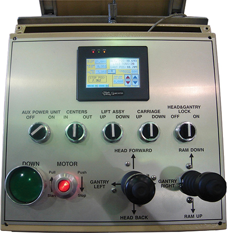
Photo D: This press control, installed on a moveable-gantry press, allows the operator to view actual main-ram position, and then input the desired pressing depth in increments of 0.001 in.
4) Head and Gantry Lock lifts the gantry (of a traveling-gantry press) up against the bottom of the press bed to hold it in place during straightening. This prevents the gantry from tipping and moving off-center to the table surface.
5) Down Pushbutton: This button is required for anti-tiedown and anti-repeat dual-hand controls, complying with OSHA requirements to keep both of the operator’s hands engaged at the start of the cycle. He places one hand on the cycle start button and the other hand on the joystick controlling ram movement.
6) Motor On/Off button turns the motor on and off. In the off position, all pressure is removed from the system.
7) Gantry Movement Joystick Control allows the operator to jog the head of the press (cylinder assembly) front and back, while allowing the gantry to move left and right. The gantry can be positioned over a predetermined area of the press bed to allow the operator to finely control where he wants to engage the part for straightening. Some gantries only allow for X-axis movement (typically for shaft work), and others allow for X- and Y-axis movement (for plate or weldment work).
8) Main Ram Joystick Control: This joystick controls main-ram extension and retraction; the ram also is proportionally controlled for speed and pressure. MF
See also: Greenerd Press & Machine Co.
Technologies: Pressroom Automation, Stamping Presses
