System Components
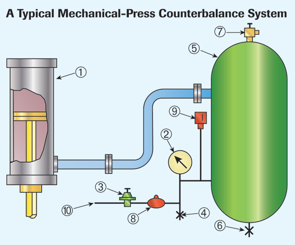
Fig. 1 shows the major components that make up a mechanical-press counterbalance system. The counterbalance cylinder (1) includes a piston rod that attaches to the press slide and counterbalances the weight of the slide and upper die. Included is a pressure gauge (2) designed specifically for press-vibration duty. An adjustable air regulator (3) on the press permits accurate adjustment to the correct setting. Bleeding the system occurs quickly by opening the blow-down valve (4).
Other components include:
• 5—Surge tank or tanks, built to ASME pressure vessel code
• 6—Accumulated water drain valve
• 7—Tank safety pop-off valve
• 8—Check valve
• 9—Low air pressure switch
• 10—Shop air inlet.
Many presses have two cylinders for each slide (5). Double-action presses have separate counterbalance systems for each slide.
The check valve (8) prevents a sudden loss of pressure from the counterbalance system in the event of an air-source failure. In addition, the pressure-actuated switch (9) will open the main motor run circuit should the pressure fall below a minimum value specified by the press manufacturer. This ensures that the press will not run without enough air to balance the slide alone.
Note: Never adjust the pressure switch below the required minimum setting specified by the manufacturer, or bypass the switch with a jumper wire. If the correct counterbalance pressure cannot be maintained, erratic press operation may result. Several likely causes include:
• Low shop air pressure;
• Excessive air leakage; or
• An accumulation of water in the surge tank.
Documenting Pressure Settings
To manually adjust counterbalance systems, operators use a pressure regulator to set the counterbalance pressure to a value that will correctly counterbalance the weight of the slide and its attachments (upper die, risers, parallels, etc.). Doing so requires three key ingredients:
1) The diesetter must know the weight of the upper die, including any buildup.
2) He also must have an accurate table of pressure settings for the upper die weight. The metalformer should provide this information on a metal tag supplied with and attached to the press.
3) The pressure gauge must be accurate, and periodically tested.
Most presses include a chart that specifies the correct pressure setting for various upper die weights. If the information is missing, contact the press manufacturer. If this is not possible, determine the correct settings by performing the required tests or engineering calculations.
OSHA requires that the information regarding upper die weight be made available to the diesetter when necessary for proper air counterbalance-pressure adjustment. This will promote safe die handling and counterbalance setting. Stamping the upper, lower and total die weight on the press is the required method, unless the metalformer can show a foolproof alternative —such as written instructions, stating the upper die weight, being readily available to the diesetter.
Further, the total die weight must be known to avoid overloading die-handling equipment. OSHA regulations specifically state “stamped” rather than marked or painted, as there is als a danger that an incorrect figure may be repainted on the die.
Should the chart on the press listing air-pressure readings for different upper die weights be unreadable or missing, stampers should develop a new one. If a paper chart is used, keep a master copy in an office and hang a copy—placed in a protective plastic sleeve—near the counterbalance at the press.
Automatic Pressure Adjustment
Some newer and retrofitted presses designed for quick die change (QDC) feature automatic counterbalance adjustment, based on a computerized database of die-identification numbers. These systems can maintain the correct pressure under production conditions by compensating for expansion of the counterbalance air due to packing friction. In most cases, the metalformer must determine the correct pressure and enter it into the database. Be sure to update the database when needed, rather than relying on manual adjustment after problems develop.
Press controls based on programmable logic controllers, dedicated microprocessor-based controls, and industrial computers for setting press operating parameters can prove highly reliable. It is essential, though, that stampers correctly enter the data and carefully maintain all system functions.
QDC is a goal that all stampers should strive to achieve. Retrofitting to modern integrated press controllers having tonnage-monitoring capabilities together with automatic shut height and counterbalance adjustment can improve diesetting time, provide consistent setups and greatly improve press uptime.
Lubrication
Counterbalance lubrication must be supplied to the cylinder-piston packing and to the rod-gland packing. Dry piston packing on large presses may emit a characteristic sound best described as that of a cow mooing. If the problem is not promptly corrected, the packing will fail.
Lubrication is either supplied by a manual hand pump or metered automatically. In both cases, ensure that the correct lubricant is applied as needed. This must be part of a total preventive-maintenance program. Properly lubricated, the packing should provide decades of service. Should a stamper allow the rod-packing gland or piston packing to run dry, the packing will fail and the rod, piston and cylinder body will become scored—prepare for downtime and expensive repairs. MF
The author expresses gratitude to Jim Barrett, Link Systems, and Dan Falcone, Toledo Integrated Systems, for contributing to this article. Technologies: Stamping Presses