Metal-Scrap Shaker Systems

September 1, 2016
0
Comments


When metal-stamping plants are fully operating, everything moves quickly. Sheetmetal coils feed presses at throughput rates of 100 parts/min., or more. After each punch, metal trim falls away through the die, collected as scrap for recycling or sale. But all of that production can quickly come to a halt if scrap cannot be effectively cleared away.

Frequent, unscheduled repairs and breakdowns of scrap-collection systems can disrupt production, costing as much as $1000/hr. in idle time. If a press is processing 60 parts/min., as many do, that’s also 3600 parts that aren’t being made for each hour that production is shut down. Shipments can be delayed, customers can become disappointed and reputations can suffer.

 
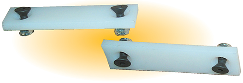
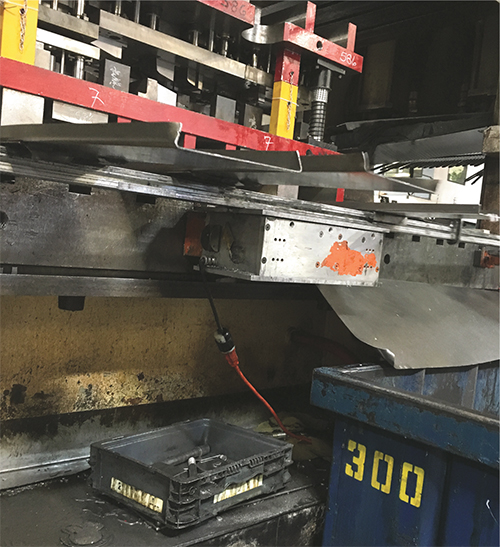
This shaker installation has an 8-ft. crossbar, but was designed and engineered for a crossbar no longer than 3 ft. It also exhibits uneven pan load—two pans on the left and one on the right. And, the crossbar lacks supports on its ends to control twisting.
A better solution: an 8-ft. rack-and-pinion setup.
This article aims to help maintenance managers and process engineers understand how to address the most common causes of failures in shaker systems, while helping them understand the advantages electric shaker systems have over pneumatically driven systems. These guidelines can help readers make the business case for updating scrap-clearing systems to the most cost-effective electric shaker models. For plants operating older conveyor-belt systems, this article also can help justify selecting electric shaker systems as replacements worthy of investment.

The Four Common Causes of Failure

Few industrial processes are as hard on equipment as metal stamping. With the continuous pounding and applications of extreme physical forces along a plant production line, reliability is critical to throughput and uptime. This extends to scrap-clearing and collection systems. They’re subject to the constant drop and bounce of scrap metal, with varying weight loads as scrap is cleared, collected and disposed of.

Based on the experience of designing, engineering, installing and servicing scrap shaker systems, we have found most failures of these shaker systems have root causes in four key areas: uneven pan loads, jams, insufficient pan support and leveling, and poor pan installation.

Uneven pan loads—Basic physics suggests that uneven pan loads can stress shaker systems designed for more balanced loads. Operators should ensure that an equal number of pans are installed and evenly spaced on each side of a shaker-system’s crossbar. If not, the uneven weight load of scrap metal can cause the top plate of the shaker system to twist with each movement. This twisting action can put extra stress on the system’s motor and bearings, causing them to fail. For those applications that require uneven pan loads, users should opt for a rack-and-pinion system that utilizes an extrusion at the end to prevent twisting movement from the uneven loads.

Jams—Scrap or parts falling through a die can bounce and end up in various places around the press. These pieces can jam between the shaker-system’s pans or drive components. Watch for jams and quickly clear them to prevent excessive wear on the motor and its linear bearings.

Insufficient support and leveling of pans—Be sure to install pans level with the press bed. Inclining or declining pans can add unwanted torque to the motor, creating excess wear. To better support pans and reduce friction from metal-on-metal contact, ultra-high-molecular-weight (UHMW) polyethylene pads or lining can be used.

Poor pan installation—Pans that are crooked, loose or banging against other objects can create additional operating stresses that can lead to premature bearing or motor failures. A solid installation can be achieved several ways.

One solution is to use quick-release pan-mount brackets. These brackets will lock down the pans securely while also allowing operators quick and flexible changes to pan placement. Lastly, the crossbars that the pans mount to should not exceed the manufacturer’s maximum recommended length.

Performance and Cost Advantages of Electric Shaker Systems

When properly installed and maintained to eliminate the common causes of operating failures noted above, electric shaker systems can provide years of trouble-free service. They also can deliver significant performance and cost advantages over their pneumatically driven counterparts. The advantages listed below can provide a compelling business case to make the switch.

Efficiency—By eliminating the disruptions caused by the frequent maintenance and repairs required by pneumatic shaker systems, electric shaker systems can provide plant engineers an immediate and significant boost in plant efficiency. Wasteful leaks in air tubing, which can run thousands of feet, also are eliminated, along with the need for air compressors, which can free up valuable plant floor space.

Electric Shakers Replace Pneumatics at Radar Industries

When Radar Industries, Warren, MI, was acquired in 2014, it operated three stamping plants. Across them were 17 presses, ranging from 300 to 2200 tons, which stamped interior, chassis and powertrain components for the automotive industry.

When pneumatic shaker technology first appeared in the late 1990s, the company deployed the systems to clear away scrap metal of varying sizes and shapes. However, the mounting costs associated with their maintenance and repair, which resulted in downtime ranging from 50 to 60 percent per shift, eventually became intolerable in plant operations. Not only was maintenance staff constantly responding to breakdowns, but production delays were affecting the company’s delivery schedules.

After careful evaluation of alternatives, the company replaced its pneumatic shaker systems with electric systems (from MPI). The electric shakers have eliminated the costly and disruptive downtime and operating expenses of the older pneumatic systems. And, aside from periodic inspections for infrequent scrap jams, the systems virtually are maintenance-free, which gives the maintenance staff time to focus on more important matters affecting plant operation.

Reliability—Despite the harsh operating conditions that electric shaker systems are subjected to in metal-stamping plants, they’re designed, engineered and built to be extremely reliable. For example, many models avoid using seals and damping components that can require maintenance and repairs. Pneumatic models are more complicated, with more parts and assemblies that can break down.

Simplicity—Pneumatic systems require compressed air from compressors, often located far from the stamping machine. The compressors, tubing and connections with the shaking systems constitute a complicated infrastructure that requires lubrication, plus periodic and as-needed maintenance and repair. Electric shaker systems can operate virtually maintenance-free with longer service intervals and fewer spare parts.

Energy savings—Electric shaker systems use 71-percent less energy compared with a 3.4-cu.ft./min. pneumatic system. Given the number of stamping presses in a plant and how long they run—assuming their scrap-handling systems run at the same time —the annual energy-cost savings from electric shaker systems can run in the tens of thousands of dollars, depending on local electricity costs. Less energy consumption also can translate into reduced carbon emissions.

Maintenance—Electric shaker systems are virtually maintenance-free, enabling staff to focus on other maintenance tasks. Pneumatic systems require regular lubrication of their air lines and seals to prevent leaks, and this maintenance must be conducted over the many thousands of feet of tubing typical in medium and large stamping plants.

Flexibility—Electric shaker systems typically are designed, engineered and built for industry-standard T-slot configurations typical of most stamping plants. This helps simplify any necessary reconfiguring of the production layout. For even more deployment flexibility and help with compliance of minor alignment issues, some electric shakers use rubber suspension technology that provides several functions in a single unit, such as those provided by torsion springs, pivot bearings and anti-vibration mounts.

Less noise—Noise in stamping plants is a given and an environmental condition that’s subject to limits set by OSHA. But it’s an even bigger issue if pneumatic shaker systems are in place with loud air bursts each time trim gets cleared. Electric shaker systems operate almost silently thanks to their relatively small motors.

Extensibility—As momentum for smart manufacturing builds, manufacturing plants increasingly are modernizing their digital command-and-control systems with field-level sensors and production-floor controllers. These devices communicate with higher-level manufacturing-execution systems. Electric shaker systems can be configured to connect into these networks.

For example, although most electric shaker systems have a simple on/off switch or are wired into the press, a variable-frequency drive could provide finer control of the shaker motor’s operation. Also, a sensor could monitor the amps of a shaker to warn plant operators that a jam has occurred. A technician then can be dispatched to manually clear the jam before scrap backs up and causes a press shutdown.

Proper Installation and Maintenance for Trouble-Free Operation

What’s clear from helping hundreds of metal-stamping plants deploy electric shaker systems is that proper installation and maintenance is required to ensure trouble-free operation, to keep scrap moving and press efficiency rates high. While electric shaker systems have been available for years, many stamping plants around the world still use pneumatic systems (some still use belt conveyors) to ferry scrap for recycling or sale. As a result, they suffer the costs and consequences of increased production disruptions, as well as high maintenance and repair costs.

Experiencing disrupted production caused by the failure of a pneumatic shaking system unfortunately is not an isolated case. (See the accompanying case-history sidebar.) One study showed that while an electric actuator might cost as much as five times that of a pneumatic actuator, the extra capital cost usually is recovered within 12 months of deployment. MF

Article provided by MPI, Highland, MI; 248/887-5600, www.mpimagnet.com.
Industry-Related Terms: Bed, Case, Die, Lines, Plate, Run, Scrap, Torque, Twist
View Glossary of Metalforming Terms


See also: Magnetic Products, Inc.

Technologies: Coil and Sheet Handling, Pressroom Automation

Comments

Must be logged in to post a comment.
There are no comments posted.

Subscribe to the Newsletter

Start receiving newsletters.