A Duty-Cycle Reality Check
January 1, 2018Comments
 When it comes to arc-welding power supplies, we hear a lot of talk about duty cycle—and plenty of misinformation related to compact integrated inverters (the type with a built-in wire feeder) as not being true “industrial” welding machines. This article addresses that topic, and provides two critical reality checks.
We measure rated output or “size” of a welding power supply using amps, volts and duty cycle. Duty cycle, evaluated using a 10-min. cycle time, represents the amount of time a machine can operate at a given output without exceeding the temperature limits of its components. For example, a power supply with a duty-cycle rating of 40 percent when gas-metal-arc welding (GMAW) at 285 A/28 V can weld continuously for 4 min. at 285 A/28 V. It then must cool for the remaining 6 min. Thermocouples in the power supply measure temperature; to protect the components, they will shut the machine down when necessary. You may actually be able to weld before the end of the 6-min. cooling cycle if the components are cool enough, but not at full-duty cycle.
Three factors to consider:
- Duty cycle and welding output are inversely proportional. When welding at lower outputs, duty cycle increases. For example, when GMA-welding at 220 A/25 V, duty cycle increases to 60 percent.
- We evaluate duty cycle at a specific ambient temperature—typically 104 F. In cooler ambient temperatures, duty cycle increases. For example, when welding at 70 F, you could experience close to a 100-percent duty cycle—specifics will vary by machine and actual parameters, but welding in cooler temperatures definitely boosts duty cycle.
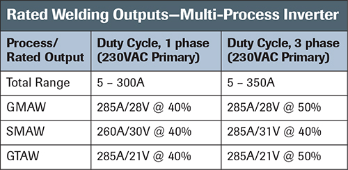
- With a multi-process, multi-voltage power supply, duty cycle and welding output will vary by process and input power (see the chart).
Other Considerations: Electrode Capacity
 In most applications, the current-carrying capacity of the welding wire or electrode dictates maximum welding output. In turn, the electrode selected must match the requirements of the welding process, as well as the weld-bead profile, metallurgy, mechanical properties and acceptable heat input.
For GMAW of steel ¼ in. and thinner, 0.035- and 0.045-in.-dia. mild-steel electrodes often suffice. The recommended parameters for short-circuit GMAW on 1/4-in. steel: 180-190 A, 21-22 V. For spray transfer: 200-210 A, 24-25 V.
In production situations, the inverter referenced above has plenty of power. In fact, it can produce more welding output than a 0.035-in. electrode can handle. While a 0.045-in. electrode can be used for spray transfer 350 A with a 92 Ar-8 CO2 shielding gas, that much heat would be unsuitable for the sheet thickness at hand.
Work Flow
The nature of most welding projects requires numerous work stoppages, especially during gas-tungsten-arc welding (GTAW). Think about all of the things that require an operator to stop welding: change rods, grind welds and remove slag and silica islands, complete the joint, reposition the body, rest to prevent hand fatigue, etc. Every time the welder pauses, the power supply cools down and the duty cycle resets. Even in industrial settings, actual arc-on time rarely exceeds 25 percent.
Please note that we do not recommend a 285 A, 40-percent duty-cycle inverter as the best solution for most industrial applications. However, the conversation needs to change. For GMAW with a 0.035- or 0.045-in.-dia. wire using conventional processes, a welder could pull the gun trigger and the only reason he might stop welding would be to change the wire spool. Duty cycle will not be the issue. MF
View Glossary of Metalforming Terms
See also: ESAB Welding & Cutting
Technologies: Welding and Joining