


Many stampers run coil and blanks in the same press, and some transfer-press systems deal efficiently with both conditions. The physical characteristics of the transfer system, along with the flexibility of the electronics, allow press lines to load blanks in one direction, and then run coil from the other direction. MF
|
Proper Transfer-Die Design
Top transfer-system performance demands that tooling matches well with press-line equipment. That means providing information to the die designer at the beginning of tool design. The following information should be provided: 1) Press specifications—tonnage, bed size, strokes per minute (fixed or variable), stroke length, shut height, type of drive, scrap opening locations, size of windows. 2) Transfer specifications—make, type of drive (servo or mechanical), pitch length (minimum and maximum), clamp length (minimum and maximum), lift height (minimum and maximum), speed or control limitations, weight of bar and fingers (if available), length of part life in years. 3) Part specifications—material, thickness, complete data on part shape, tolerances, volume required per hour/day/month. 4) Miscellaneous information—quick-die-change system with description, frequency of changeover, feed method (coil or blank) and feed method’s accuracy, drop-off or finished part, lubrication specifications and amount, critical finish areas. 5) Sample parts or sight model.
Design Suggestions Before tooling-design work begins, consider the following die construction principles:
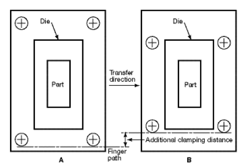
Guide-pin or heel-block locations. Traditional die-design principles suggest that pins or heel blocks be located as far outboard as possible (Fig. 1). This allows for the longest lever arm between the contact points, keeping the upper die parallel with the lower die during operation. This works well with progressive dies, which contain all motion inside the die, or with line dies, which allow the operator to work between the die pins. But with most transfer systems, this front-to-back location results in a longer clamp stroke—due to a finger return path located outside of the pins—and a slower transfer speed. Left-to-right pin locations usually are dictated by part and die size. Efforts typically are made to orient the part with its minimum dimension in the left-to-right direction (direction of flow) to obtain the required number of stations in the press and to maintain a minimal stroke distance. For a large press producing small parts, the dies may have to be oriented close together in the center of the press—with the loading system if feasible—or idle stations may need to be added to keep the stroke short. Guide-pin and heel-block heights. Guide pins or heel-block posts should reside in the upper die shoe, with bushings or heel blocks located in the lower shoe. However, bushing and heel-block heights, as well as guide-pin lengths, often are ignored. While not a problem with progressive or line dies, a transfer die requires short pins and heel blocks so that transfer fingers can move as soon as the die begins to open. Long pins or heel blocks force the system to wait longer for a clear path, providing less overall time for the transfer operation. When the fingers must move faster, part control often is lost; or if the press is slowed, productivity suffers. If pins or heel blocks are shorter on the top die and taller on the bottom die, and the engagement point resides near the passline of the transfer, the clear path occurs earlier. This allows more time for transfer motion, resulting in faster press operation. Stop-block locations and heights similarly should be considered in transfer-die design. Lower die profile. Rather than run the movement of the transfer with square corners at the transition of lift motion and stroke motion, most servo transfers can round the corner—essentially overlapping between the two motions. This is possible where no interference exists between the fingers or the lower surface of the part and the lower die. More clearance allows greater overlap, creating a larger radius and making transition from lift to stroke smoother and faster, increasing output.
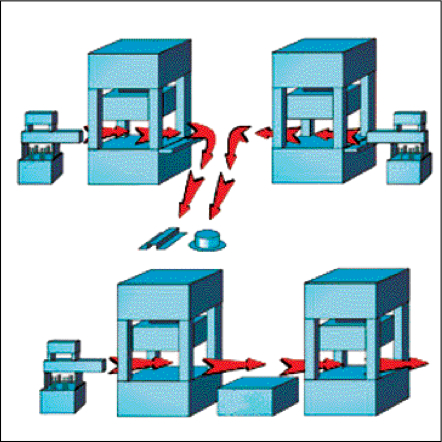
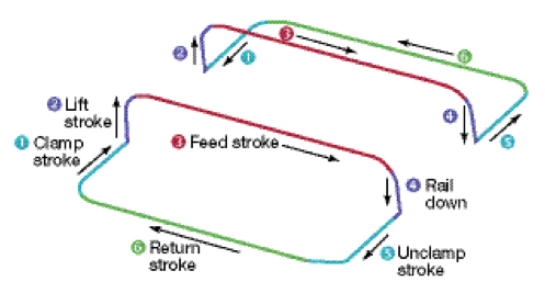
Finger return path. Critical for transfer-die design, clearance between fingers and die components during the return stroke of the transfer must be analyzed to ensure no interference. Clearance issues for mechanical transfers are even more critical, as servo transfer systems can vary the return profile of the fingers, allowing more clearance possibilities. All of these suggestions save time by reducing travel distance of the fingers, beginning transfer motion early in the cycle, or rounding the corners of various motions (Fig. 2). At a fixed press speed, these improvements slow finger motion and reduce the chance that part control will be lost. |
View Glossary of Metalforming Terms
See also: Gudel, Inc.
Technologies: Stamping Presses
