


And we’re just getting started. Specifiers of transfer systems also must account for the amount of travel required in the y, or clamp, axis. For example, say the bars are required to move 5 in. per side in that axis. That takes a another 10 in. of window opening. Now consider the length of the finger tooling. Let’s assume for this example that the fingers would measure 5 in. With finger tools on both bars, another 10 in. of window opening disappears. The total? With a 50-in.-wide window opening, a through-the-window transfer could limit you to a maximum 21-in.-wide coil or blank in that press.
On a front-and-back transfer system, the bars do not travel within the upright openings of the press. With these transfer styles, the only limiting factor is the front-to-back press-upright opening itself. That is one of the big benefits of this style of transfer over a through-the-window unit.
Where’s the Feed?
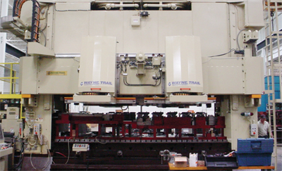
Front-and-back-mounted servo transfer systems feature transfer assemblies placed in the front and back of the press, allowing the press upright window openings to be completely unobstructed, therefore, not limiting the material width of the coil or blank fed in through the window.
If the system is coil-fed, feed positioning also should be considered when deciding between a through-the-window transfer and its front-and-back-mounted counterpart. A through-the-window transfer has a permanent finger bar attached to each of the transfer assemblies mounted on each end of the press. Those bars travel outside of the press area, requiring the user to position feed equipment a from the press to provide bar clearance. Front-and-back-mounted transfers don’t have this arrangement, enabling feed equipment to be positioned right at the press.
Besides occupying valuable floorspace, with a coil line positioned a from the press, actions such as tailing out the end of the coil can create more scrap. And suppose a stamper wants to retrofit an existing press and feed line with a servo transfer system. The feeder may already be mounted at the press, complete with a looping pit and other equipment. Installing a through-the-window transfer would require foundation work to accommodate a new pit location, let alone the work of relocating the entire feed arrangement. Doing so adds significant time and cost to the project.
Independent Bar Control a Plus
Front-and-back-mounted transfers have an additional advantage. These arrangements are comprised of essentially two transfer assemblies, operating independently of each other and not mechanically tied together, as is the case with through-the-window models. So they can be programmed for different move parameters in the x, y and z axes, making front-and-back-mounted transfers conducive to outside-the-box thinking in terms of die arrangements. This setup eases two-lane production, where two lanes of dies run within the press to simultaneously produce left- and right-hand parts, or double the production of the same part. Two-lane production is possible with a through-the-window transfer, but independent programming of each bar’s movement makes it easier on front-and-back-mounted units.
Another of increasing press capacity is by configuring the die in a U-turn arrangement. In this scenario, the part is transferred through a series of dies in one direction, then shifted 90 deg. to a series of dies in which the part transfers in the opposite direction. The benefits of this arrangement are many. The press-bed-length capacity is doubled, the need for a secondary press operation can be eliminated and the possibility of utilizing an existing smaller bed press now is attainable. This type of die arrangement is typically better suited for a front-and-back transfer versus a through-the-window transfer because the part must be pitched in opposite directions simultaneously, requiring independent movement of each pitch-axis transfer assembly.
On larger presses, front-and-back-mounted transfers allow for multiple transfer assemblies, enabling different pitch, or x-axis, distances between die sections. That allows for closer die spacing, thus shortening the left-to-right bed-size requirement for a particular die. For example, in press beds more than 180 in. long where multiple transfer assemblies can be applied—say two on the front of the press and two on the rear—the modules can be programmed for different move parameters in their x axis between die sections. Given a 10-station die, the first five die stations can have a centerline pitch requirement of 30 in., but the pitch distances centerline to centerline of the last five stations can be shortened to, say, 25 in. This can allow for a shorter die design, thus requiring a shorter left-to-right press-bed dimension—or on an existing press, sufficient room to place one more die in the process if needed. This ability for closer die spacing enables a die previously considered too long for a press to fit into that bed.
Consider Press-Bed Access for Die Work
For all the benefits of front-and-back-mounted transfers, stampers should be aware of potential drawbacks. Presses with doors that enclose the press window during production require modification to accept these transfers; not the case with through-the-window units.
Die change also becomes more challenging with front-and-back-mounted transfers. The transfer assemblies occupy the areas most frequently accessed by towmotors to place or remove dies. Options are available to metalformers to raise the assemblies toward the crown or off to the side to open up press access. Through-the-window transfers provide clear and unobstructed access at the press front and rear openings. MF
View Glossary of Metalforming Terms
See also: Lincoln Electric Automation
Technologies: Stamping Presses
