Seven Basic Tips for Implementing a Robotic Welding Cell

January 30, 2019
0
Comments


Robotic welding can significantly improve your manufacturing operation’s productivity and weld quality, saving time and money spent making fixes and improving processes, so long as you know and practice the basics. From choosing the right welding wire to establishing a proper tool center point, many variables play a role in optimizing robotic-welding cells.

The following tips for setting up a cell help establish repeatable and consistent process, resulting in quality welds, reduced rework and maximized investment.

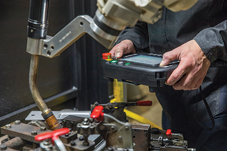
1. Use Proper Weld Settings

Factors such as wire size and material thickness determine proper weld settings. Some welding power sources offer technology that allows welders to input the wire size and material thickness, with the machine suggesting recommended parameters for the application.

Without this technology, finding the correct parameters involves trial-and-error. Sometimes the robot manufacturer, welding-power source manufacturer or system integrator can assist in choosing and testing specific materials to provide a starting point for the proper welding parameters.

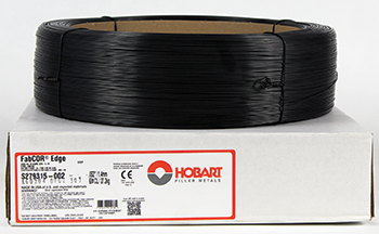
2. Choose the Right Wire


From choosing the right welding wire to establishing a proper tool center point, many variables play a role in optimizing robotic-welding cells to produce the best results.
The choice of filler metal for a robotic-welding system can impact productivity, weld quality and overall investment. Material type and thickness, as well as the expected outcomes for the welded part, are important considerations when selecting the wire. Welding-equipment and filler-metal manufacturers often offer charts to help match welding wire to process needs.

While solid wire has been the industry sta-dard in robotic welding for many years, metal-cored wire provides an alternative that offers productivity and quality improvements in some applications, particularly in the manufacture of heavy equipment and automotive exhaust systems, chassis and wheels. However, each wire type offers pros and cons for certain applications.

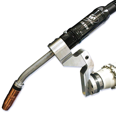
3. Consider the Gun and Consumables

Robotic-welding guns and consumables, including the nozzle, contact tip and gas diffuser, greatly impact performance. The right combination reduces unplanned downtime and improves overall cell efficiency.

Robotic-welding systems, typically operating at higher duty cycles than semiautomatic welding applications, may utilize transfer modes known to be especially harsh on gun consumables. As a result, use of more heat-resistant, heavy-duty consumables, such as chrome zirconium contact tips, or tips designed for pulsed-welding processes.

Verify that the welding gun’s duty-cycle and amperage ratings meet application requirements. To avoid excessive wear and premature failure, the gun should not rub against any part of the system or another robot in multi-robot applications.


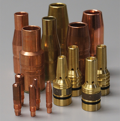
Welding consumables, including the nozzle, contact tip and gas diffuser, have a huge impact on performance in the robotic-welding cell. Consider using heavy-duty consumables that are more heat-resistant than standard-duty consumables.
Also, ensure proper installation of consumables. Improper or loose connections produce more electrical resistance and heat, causing faster consumable wear with premature failures. Another common failure in robotic welding: improper liner installation. Always follow the manufacturer’s directions for liner installation and cut length. A liner cut too short can cause premature failures of other consumables in the system.

4. Reduce Cable Wear

Good cable grounding in the weld cell helps prevent potential problems as the cell ages. Two cables run from the welding power source: one attaches to the wire feeder and the other to the tooling. These cables, often long, may travel from the shop floor to an elevated platform or through wire trays. The section of cable running up the robot or to a positioner will move constantly, causing greater wear over time.

Using a junction with high-flex ground cable at the base of the robot or the workpiece helps reduce downtime and repair costs, requiring only the replacement of a 6-ft. cable section, when worn, rather than replacing perhaps 50 ft. or more of ground cable running all the way back to the power source. However, you should have as few breaks or junctions in the grounding cable as possible to maintain a better electrical connection.

When mounting a ground cable to the welding workpiece, use copper anti-seize lubricant, sometimes referred to as copper slop. This supports the transfer of electrical current and helps prevent the mounting point from fusing together or deteriorating over time. The lubricant assists in all areas where grounding current may run run through pins or other semi-permanent contact points.

Proper gun-cable management also extends cable life. The more any cable bends and flexes, the more it will wear and tear, ultimately shortening cable life due to high heat and resistance. Minimize cable bending and flexing in your robotic process and tooling design.

5. Establish TCP


Verify that the welding gun’s duty-cycle and amperage ratings meet application requirements. To avoid excessive wear and premature failure, the gun should not rub against any part of the system.
For repeatable and consistent weld quality, establish and maintain proper tool center point (TCP). Welding operations can set their own standards for the acceptable amount of TCP drift, depending on the application and type of weld. When considering the tolerance of TCP variation, half the thickness of the wire diameter represents an acceptable starting point.

Many robotic systems today use touch-sensing features to monitor TCP and determine how far it has moved from the original programmed settings. If determined to be out of the acceptable TCP range, the gun neck can be removed and recalibrated offline to factory specifications with a neck straightening fixture. Some systems also provide the ability to adjust TCP automatically with the robot. A third option: Leave the gun in place and adjust the robot teaching path to accommodate the modified TCP, though this is the most time-consuming solution. It also requires the need to reprogram the robot if new factory specifications for TCP or a new neck are introduced, making this method the last resort.

Whether every weld cycle, once per shift, or every time the torch goes through a reamer cycle, set a schedule or standard for checking TCP. This practice saves money in lost scrap and rework should a problem occur before welding.

6. Program the Robot Path

The initial programming of the robot’s welding path also involves much trial and error. When programming the path, consider the application, material type, welding process and gap size to be filled. Also impacting weld quality and amount of spatter: travel angle and whether it’s a pull or push weld.


The choice of filler metal for a robotic-welding system can significantly impact productivity, weld quality and the overall investment. Material type and thickness, as well as the expected outcomes for the welded part, are important considerations when selecting the wire.
After setting the home positions in the robotic program, have the robot move to perch points or ready-to-enter points away from any potential collision points, so that the system can move quickly with air-cut moves to and from these points.

When programming the robot to move to a weld, it’s common to set the approach point just above the weld-start location. Have the robot approach the start location at a slower and safer speed with the arc on. This approach position provides a good lead-in and typically won’t require adjustment unless the weld location moves. Some robotic-welding systems include technology that aids in setting the initial robot path.

The robot’s welding location plays a role in premature gun failure. Robotic welds with a lot of flex in the gun at a tight angle can cause the gun to fail much faster. Minimizing robot axes to five or six during welding helps extend gun life by reducing wear.

7. Ensure Proper Fitup

Critical to consistent weld quality and robot-path programming: proper part fitup in the upstream process. Inconsistent fitup or large gaps between the parts lead to weld-quality issues such as burnthrough, poor penetration, porosity and others—resulting in additional unplanned downtime to deal with these problems. Large gaps between the parts also may require double weld passes, adding to cycle times. MF

Industry-Related Terms: Bending, Center, Fixture, Penetration, Point, Run, Scrap, Spatter, Thickness, Tolerance, Transfer
View Glossary of Metalforming Terms


See also: Tregaskiss

Technologies: Pressroom Automation, Welding and Joining

Comments

Must be logged in to post a comment.
There are no comments posted.

Subscribe to the Newsletter

Start receiving newsletters.