Tubular Framing
Construction of the weld tooling itself can combat challenges related to weld heat, slag and spatter, while still allowing access for part handling and welding. Consider, for example, a fixture built on a flat plate—spatter quickly builds on the base plate of that tooling, causing downtime for cleaning or repair.
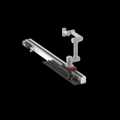
As an alternative, consider placing fixtures on a tubular frame. Such construction enables simplified weld access—users can roll over the tubular fixture frame to access the back side of the assembly for welding, or for system maintenance. Conversely, incorporating weld access on a flat-plate fixture base requires placement of holes in the plate, which can limit torch access. Even then, spatter-buildup issues remain. With a tubular frame, spatter generally falls to the floor without accumulating on the weld tools. Further, with a tubular frame the fixture builder can include access holes in the tubes of the frame to allow sensor cables, other wiring and plumbing to be run inside of the tubing. With the access holes then covered, the tubes provide slag and spatter protection. If access holes aren’t an option, wires on the fixture frame allow sensor cables and other lines to safely route back to a control panel, still protected from slag and spatter. Quick-Change Capability The automotive industry does not like inventory; it’s all about just-in-time. Though component and assembly volumes may be high, parts may be run only a couple of hours at a time. Fabrication of part families, where sets of parts exhibit slight differences, also limit run volumes. These situations demand quick tool changeouts, as idle machines aren’t profitable. Well-designed fixturing enables rapid changeout. To save time, especially during part-family work that involves minor part-feature changes from run to run, sections of weld tooling can be replaced without exchanging the entire fixture setup. Robotic tool changers, with a manual assist, can be employed to change out tooling sections. Users press a button on the automation cell’s human-machine interface to release the tool changer, then pull out the section and replace it with a new one. Pressing another button energizes a clamp in the tool changer to hold the new section in place, and welding resumes after only a few minutes. To further facilitate changeout, the ideal weld-tool setup includes quick disconnects on air and electrical lines, as well as plug-and-play communications components. These setups can make quick work of large weld tools, too, with automated systems to carry the behemoths in and out of the weld cell, and a positioner to hydraulically clamp the tool in place. Even though parts must meet certain tolerances, some unexpected variation occurs, especially when a user welds parts that arrive from different suppliers. To assist in changeout and production in these instances, tooling may be shimmable in positions along x, y and z axes. Allowing users to slightly shim the fixtures accounts for part variation and enables rapid return to production. Staging of fixtures and changeout tooling assists in quick-change operations, as well. To maintain production levels, metalformers should stage parts as closely as possible to the weld tools. A well-designed process allows parts to be brought in on carts that integrate with the safety zone of the weld cell. And, following the welding process, oftentimes cell operators will remove the assemblies and place them on racks. To prevent operators from becoming bottlenecks in the process, systems increasingly implement robots to handle completed welded assemblies. A robot with a gripper may come in and pull the final assembly out of the fixture from the back, as the operator prepares the next assembly in the front of the weld cell. The robot takes care of removal and may even perform additional operations on the assembly before depositing it on a conveyor. Fixturing Evolves to Handle Increased Complexity, and Laser Welding Automotive seat frames provide a vivid illustration of how welded assemblies have become increasingly complex. Only 20 years ago, most seat frames consisted of a bulky outer frame and a few wires for attachments. Today, frames are much smaller and thinner yet contain more parts and safety features than ever, including components and brackets for seat heaters and more complicated adjusting mechanisms. All of that translates to more complicated weld fixturing. In addition, high-strength steel is used in frame and structural components, requiring heavy-duty fixtures and clamps. Beyond more complicated parts and thinner materials, processes themselves require new fixturing solutions. Until recently, fixtures were designed simply to hold components, and those components had to be in-tolerance because the fixtures couldn’t force the parts together. However, as laser welding gains in popularity, fabricators must adapt by developing fixtures that bring parts together—no gaps allowed. These parts must be forced into position; now, fixturing can do that. Advanced processes such as laser welding demand tighter tolerances, thus better fixtures. For example, consider sear-frame assemblies where two pans must be welded together. A tool often referred to as a clamshell closes down on the pans to pancake them together. The gap-free components then can be laser welded, with holes cut into the clamshell for laser access. Include Tool Designers and Builders Early Given so many advances in parts, materials and processes, and the time and cost pressures inherent in automobile production, all facets of an automated-welding installation must function in concert. That includes the fixturing. Addressing challenges and concerns during weld-cell design, as well as the design of the parts to be welded, promises to save time, money and headaches. With features constantly added to parts, proper weld-tool design becomes critical to ensuring adequate robot weld-joint access. The ability to design and build tools in 3D prior to actual construction allows mockup of the welding process and simulation of robot movement to ensure proper access and clearance.
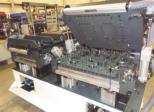
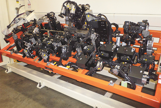
Laser welding, an increasingly popular process, can’t succeed unless parts are touching—no gaps allowed. These parts must be forced into position, and fixturing, such as this clamshell setup, reliably performs such tasks.
View Glossary of Metalforming Terms
See also: Lincoln Electric Co.
Technologies: Pressroom Automation, Welding and Joining