 |
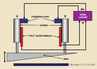
| Fig. 2—A distinguishing characteristic of many hydraulic-press applications is the requirement for two or more motion axes to move together. In this illustration of a cutoff shear press, rolled steel is sliced into segments as it comes off of the roll. Not only must the motion of the two hydraulic actuators powering the shear blade be synchronized in order to avoid binding and ensure a straight cut, the motion of the shear blade must be geared precisely to the speed of the moving steel in order to maximize throughput while ensuring a quality cut. In applications such as this, an advanced electro-hydraulic motion controller can optimally manage motion of multiple axes. |
Once the motion controller has accurate position and force feedback, it can operate in one of several modes:
1) Position control only,
2) Force control only,
3) Position or force control,
4) Position control with force limiting,
5) Position control with active damping.
Modes 1 and 2 are fairly obvious, but modes 3, 4 and 5 require explanation. First, position and force cannot be controlled simultaneously. Position or force control (mode 3) accurately controls position or force, but not at the same time. The motion controller uses different control algorithms for each mode, but the two algorithms, while running at the same time, do not interfere with each other because they don’t provide control at the same time. Typically, an actuator is initially controlled using position feedback. Then, when the actuator makes contact with the load, the controller must manage the transition into force or pressure control. This control mode provides the best of both worlds—position and force control—but has one significant drawback. Sudden removal of a load or obstruction while the system operates in force-control mode sends the actuator racing forward trying to keep force on the load cell or across the piston at the force set point. In a press application, this can damage dies if the press cycles without having a workpiece to push against. Here, no opposing force would be encountered until the top and bottom dies are pushed onto each other.
Position control with force limiting (mode 4) is preferable in many applications. In this mode, the controller causes the actuator to move until reaching either the position or force set point. This allows setting of the position set point at a safe position where the actuator will stop even if an obstruction that resulted in force being exerted has been removed. But challenges may occur in this mode when making a simple position move. Since force is needed to accelerate in position-control mode, the force-limiting function could cause the actuator to fall behind its target position. In most applications, this problem can be solved by just using position mode and ignoring force feedback during position-only moves.
Position control with active damping (mode 5) is closely related to force-limiting mode, except that instead of limiting the absolute value of force, active damping limits the rate of change of force. Active damping is critical in hydraulic applications where the natural frequency of the load and actuator is very low. Active damping reduces or eliminates the system’s tendency to oscillate by controlling or limiting the rate of change in the net force. Since net force is required to make an object accelerate, it can be thought of as a leading indicator of motion. If the force doesn’t oscillate, the load will not oscillate. But force-rate limiting, or active damping, has a limitation. When used in active damping, the force-rate limit will interfere with the controller’s ability to follow a motion profile, possibly degrading the ability to synchronize multiple axes. Nevertheless, active damping can be valuable in applications involving large masses, small-diametercylinders, or long lengths of hose between valves and cylinders.
Tackling Multiple-Axis Motion
Another distinguishing characteristic of many hydraulic-press applications is the requirement for two or more motion axes to move together, as illustrated in Fig. 2. An advanced electro-hydraulic motion controller can optimally manage motion of multiple axes.
One method for achieving harmonious multiple-axis motion, synchronization involves the coordination of multiple axes such that they all move in lock-step. With synchronized motion, position, velocity and acceleration are controlled as a function of time. This is critical in hydraulic presses with multiple actuators that must als travel in lock-step to prevent binding. The closed-loop motion controller ensures that identical moves are made on multiple actuators.
Key to accuracy of position, velocity and acceleration of synchronized axes is use of a noise-free, internally generated target profile for the axes. Synchronized axes also must be all in the same state at all times, i.e. they all must accelerate or decelerate together and stop together. In addition, if any axis halts due to a fault, the other axes must halt.
Gearing, also referred to as electronic gearing, is similar to synchronization in setting a constant relationship between the motions of two or more axes. While synchronization uses target positions generated as a function of time, with gearing, target positions are generated as a function of an external reference or an internal master axis. The external reference must generate a clean signal devoid of excessive problems such as noise, quantization error and jitter, which can degrade the performance of the geared axes.
Slave axes are geared to the master, doing exactly as the master but at a specified ratio. For example, at a 2:1 ratio, the slave axis will move 2 in. for each 1 in. of master movement. Hydraulics offers an advantage over mechanically geared systems for applications where the gear ratios must be changed on the fly. ‘Clutching’ is the term often applied to advanced gearing actions such as this. The goal of clutching is to make a gradual change in gear ratios so that the slave axis does not attempt abrupt speed changes.
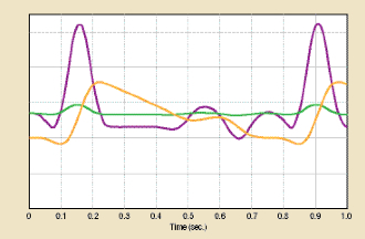 |
| Fig. 3—Advancements in electro-hydraulic motion controllers support complex motion profiles such as this repetitive motion profile, which is implemented with a single controller instruction. This motion was produced by a motion controller running a spline-curve function. The purple curve represents the velocity of the axis while the yellow curve denotes axis position and the green curve represents drive output from the motion controller connecting to the valve. |
Selecting a Motion Controller
Managing multiple interrelated motion profiles is not especially difficult given the right controller. The real trick is finding one that includes multi-axis synchronization in its standard offering, preferably as a preprogrammed function. Better yet, look for a controller with programming tools that allow graphical programming and automated tuning of the motion profile. This saves time in setting up and optimizing the system.
For proper control of multi-axis motion in complex motion systems, seek out a motion controller that allows the use of feedforward terms in the control algorithm. Feedforwards are predictive elements that allow motion systems to avoid lags due to errors between target and actual position and velocity values—smaller errors make tighter synchronization possible. Motion programmers should set up feedforwards to perform most of the control work, with feedback elements (proportional, integral and differential terms) focused on compensating for nonlinearities and environmental conditions that vary over time. For example, the acceleration feedforward function is useful in compensating for the force required to accelerate the load mass, increasing the control output to the valve during acceleration of the cylinder’s motion. This causes the valve to release more energy into the actuator, compensating for the increased kinetic energy of the load. Some motion controllers come with automated tuning tools to ease tuning for optimal feedforward and feedback functions.
New motion controllers also support powerful instructions that can ease motion-system programming. For example, hydraulic-press applications can benefit from motion controllers that support built-in motion commands producing complex curving motions. The controllers do this by interpolating data provided by the user or a host controller. Curves may be programmed to perform either time-based motion, where the curve defines the position of the axis at certain times, or master-based motion, where the curve defines the position of the axis based on a master input, such as the position of another axis. Fig. 3 shows a complex, repetitive motion profile that can be implemented with a single instruction. MF
See also: Delta Motion
Technologies: Pressroom Automation


 Video
Video