Stuart Keeler Stuart Keeler
President/owner

Understanding the Behavior of Sheetmetal

June 1, 2009
0
Comments


Highly diverse topics have been presented in this column over the past decade. In contrast, for the next half year this column will explore more deeply the fundamentals of how and why sheetmetals deform. The target audience is the personnel in metalforming companies, and especially the workers on the press floor. These personnel are being exposed to new alloys, advanced high-strength steels, new techniques to process sheetmetal into useful parts, special coatings/lubricants, and other sometimes drastic changes that conjure up questions and misunderstandings. Therefore, the explanations will be logical and readily understandable. Simple illustrations will add additional clarification. Some metallurgists may take exception to the simplicity of the explanations. However, all are designed for press-shop utilization.

The series of columns will include:

Schematic shows the multiple atomic force interactions
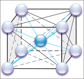
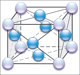
Fig. 1—Schematic shows the multiple atomic force interactions (represented as lines) between the nine atoms (body-centered cube) making up an iron (steel) unit cell.

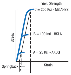
1) Elastic stresses (springback)

2) Yielding (start of permanent deformation)

3) Deformation (work hardening)

4) Failure (necking and fracture)

5) Forming limits (total elongation and forming limit curves) and

6) Surfaces (roughness and coatings). This month covers the fundamentals of elastic stresses and springback.

Understanding springback begins at the atomic level. Elastic stresses hold the atoms in place in the unit cell (Fig. 1), which is iron with a very small amount of carbon. The spheres represent iron atoms. Since the unit cell for iron has the body-centered cubic (BCC) configuration, there are eight corner iron atoms (pearl spheres) and one central iron atom (blue sphere). Each unit cell shares its six faces and corner iron atoms with six adjoining unit cells. This configuration replicates itself until a sheet of steel has length, width and depth.

The lines connecting the spheres in Fig. 1 depict the elastic stresses that bind the atoms together. Instead of lines of elastic stress, now visualize the iron atoms to be connected by tension/com-pression springs. Applying an outside force to the metal causes the spacing of the atoms to increase (tensile force) or decrease (compressive force). This creates a change in the stress between the atoms and an unstable state maintained only by the outside forces. Removal of the outside forces allows the elastic spacing between atoms to return back to their stable positions, causing the metal to springback to its original shape. The springs are still extended or compressed under load, but are back in their initial condition that balances the unit cell to its least energy state. A common concept is that the metal is attempting to return to its original shape. This is true only if no plastic (permanent) deformation or shape has been added that prevents the metal from returning to its initial state. Examples are hemispherical domes, closed end channels, deep-drawn cups, and other shapes that mechanically do not allow the return of the sheetmetal to its initial state. In this case, some elastic stresses cannot return back to their initial stable, lowest energy state. These remaining elastic stresses are called residual or trapped stresses.

In terms of our spring model, the springs remain more extended or compressed than normal. The excess energy is ready to release during some forming operation further down the line, during assembly and welding, or even during in-service operation. The part may be to print when removed from the die, but often will undergo major springback when trimming the offal releases some of these residual stresses. Even worse, springback may create different trimmed part shapes during a single shift. If a change to the residual stress pattern occurs during forming, the part will take whatever new shape it can to reach a new minimum-energy state. Change the length of one of the springs somewhere in the part and watch all springs rebalance to minimize the total energy. If a thin, narrow channel can twist itself into a pretzel shape to minimize energy, it will do just that.

The elastic stresses in the unit cell are very strong. Plotting the stress-versus-strain curve from a tensile test (Fig. 2), the elastic modulus line is very steep.

Fig. 2 yield strength
Fig. 2—The amount of springback is proportional to the yield strength of the steel.
Stress equals elastic modulus multiplied by strain, where the elastic modulus is the slope of the line. For steel, the slope is about 30 million psi. To permanently deform the steel, forming force must create a stress that exceeds the yield strength. To determine the relative springback at yielding, a line offset by 0.2 percent strain and parallel to the modulus line is drawn to intersect the stress-strain curves. These intersections are the yield strengths of the different steels. When the tensile test sample is unloaded, the specimen unloads back down the offset line. The amount of the springback is proportional to the yield strength, as shown by the arrows under the graph. Using the martensitic advanced high-strength steels available today, the amount of springback can be eight times the amount experienced by traditional aluminum-killed draw-quality steel. Other metals can have different unit cell configurations. For example, aluminum has a face-centered cubic (FCC) structure (Fig. 3). Instead of an atom
Schematic shows the multiple atomic force interactions between the 14 atoms
Fig. 3—Schematic shows the multiple atomic force interactions (represented as lines) between the 14 atoms (body centered cube) making up an aluminum unit cell.
in the center of the cube, an extra atom is found in each of the six edge planes of the cube. This changes the arrangements of the elastic stresses. The springs are hooked differently and the elastic response of aluminum is different compared to steel. For example, the modulus of elasticity is only 10 million psi instead of the 30 million psi for steel. The lower slope for aluminum means that for the same yield strength, aluminum will have three times the amount of springback as steel.

Right now our sample of metal has a perfect atomic structure without any atomic imperfections or discontinuities. This atomic structure is known as a single crystal. It would elastically stretch but without any permanent deformation. As soon as the load is removed, the sample would return to its original length. If a high enough load were applied, it would break like glass without any permanent deformation. The single crystal has special scientific uses, but cannot be used for automotive body panels, kitchen sinks or beer cans. Next month will explain methods of springback compensation using our elastic spring model. MF

Industry-Related Terms: Alloys, Case, Center, Corner, Die, Edge, Forming, Lines, Model, Twist
View Glossary of Metalforming Terms

Technologies: Materials

Comments

Must be logged in to post a comment.
There are no comments posted.

Subscribe to the Newsletter

Start receiving newsletters.