
AM Parts: From Inception to Inspection
October 14, 2019Comments
Creating production parts using metal additive manufacturing (AM) requires consideration of the entire process chain during product development. This journey involves several important steps.
The first step: design phase. Typically it is not cost-effective or appropriate to take an existing CNC-machined or cast part and convert it directly to an additive part. Those parts were designed to meet specific machining or molding rules, and those same rules do not apply to AM. To get the most out of AM, the part should utilize the benefits of additive such as lightweighting and creating topology-optimized models that include material only where needed. AM also enables the integration of several traditionally manufactured part components into the build of one single part, which eliminates assembly time. In addition, features within traditional parts require support structures (i.e., round holes). The removal of these support structures can be a challenge and one of the highest cost drivers of AM parts. A change in design from the outset eliminates the need for support structures. A round hole converted to a teardrop shape requires no support.
The second step: optimize part build. To achieve this, consider adjusting build parameters to ensure optimum part properties for your specific geometry. By maximizing the number of related parts built together on a tray as opposed to building just a single type of part, costs decrease.
The third step: post-processing. Here it is important to ask questions such as, “How should you go about removing the support structures?” “How do you remove trapped powder inside small channels or crevices in your part?” and “Do you need to apply any post finishing (i.e.: sand blasting, vapor polishing) to the part to improve surface finish to meet the end use needs?” For post-processing, consider stress relieving, heat treating and/or hot isostatic pressing (HIP) for reducing residual stresses, improving strength properties and reducing internal porosity. Developing the correct processing parameters for each of these steps is crucial for ensuring that parts do not deform or have less-desirable properties.
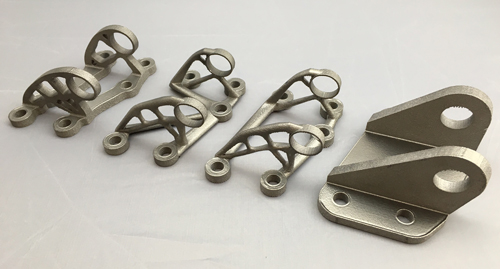 |
| Unlike the traditional CNC-machined part shown on the right, these three 3D printed parts were designed to utilize the benefits of additive manufacturing, such as lightweighting and topology-optimized models that include material only where needed. |
Another area often not considered: removal from the build plate. If parts can be built with minimal build-plate contact, removal could be an easy twist off of the plate, though this typically is not practical. More often, bandsaw or wire EDM is needed to remove parts from a build plate. Each method has its pros and cons.
An important part of post-processing to consider: machining to clean up surfaces or dial in tolerances. Most metal AM parts require some level of subtractive machining to ensure that the final parts meet final tolerances and part requirements. Often, grip points, data and more are ignored when developing the original part design. However, inclusion of such factors in the design ensures rigid holds in the CNC while processing the part.