Punching Technology—Force Limitations
August 1, 2017Comments
Calculating punching force and punch-tip pressure is straightforward. To calculate the force required to create a punched hole (Fp):
Fp = (L)(t)(σT)
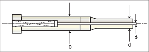
Fig. 1
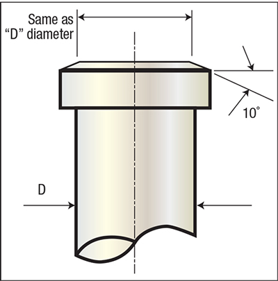
Fig. 3
Where:
L = punch-tip circumference or profile length
t = sheetmetal thickness
σT= workpiece-material shear strength
Note that metalformers may find it difficult to acquire accurate shear-strength data, and to duplicate test results. Consequently, they often will use assumptions in force calculations rather than use actual test data. For example, engineers may assume that the shear strength of mild steel equals 70 to 80 percent of its ultimate tensile strength (UTS); for aluminum, they might assume shear strength to be 50 percent of UTS; and for stainless steel, 90 percent of UTS.
However, shear strength can vary significantly within the same material type. For example, shear strength for copper alloys can range from 50 to 90 percent of UTS, depending on the alloy. As a result, calculating accurate cutting and punching forces can prove challenging, due to the lack of reliable and accurate shear data.
To simplify matters, engineers can substitute UTS for shear strength in their cutting- and punch-force calculations, but the result will be an overestimate of actual forces.
With punching force (Fp) calculated, we can derive punch-tip pressure (Pt). For a standard shoulder punch:
Pt = Fp / [(π)(½d)2]
Where:
d = the cross-sectional area of the punch tip
If the punch includes a spring-ejector pin, the cross-sectional area is reduced by the area of the hole in the punch face. To calculate the pressure on an ejector-type punch, similar to that shown in Fig. 1:
Pt = Fp / [(π)(½d)2 -(π)(½d1)2]
Punch-point performance is best when maximum point load remains below 60 percent of the compressive strength of the punch material. Compressive strength depends on the tool-steel grade and its hardness. When punch-point loads exceed 60 percent of the tool steel’s compressive strength, engineers should consider changing the punch material, adjusting heattreatment, or both.