Link Your CAD/CAM System to CNC Punching Machines
February 1, 2012Comments
Advances in software automation reduce labor content while increasing machine efficiency on the shop floor.
In today’s competitive business environment, producing parts more quickly and less costly gives sheetmetal fabricators an edge. Many businesses are trying to get the most out of the machines on their shop floor by purchasing automated material-handling equipment such as sheet loaders/ unloaders, as well as investing in new machines that can rapidly cycle hits and change tools.

While new equipment may increase productivity, if businesses are still programming their machines with their outdated or original OEM manufacturer’s software, they are not getting the full benefits from their machines. Recent advancements in software capabilities make it possible to automate the steps required to develop part designs and nests, and generate the required NC coding for plasma- and laser-cutting machines as well as CNC punch presses. This level of automation reduces manual data entry, which then reduces the required amount of manpower while increasing the accuracy of the CAD/CAM process.
To fully explain how automation can be integrated into the punching process, let’s first take a look at the individual steps involved and how each step can be improved upon.
MRP Integration
A good place to start this journey is at the beginning—incoming orders. Orders typically are received and entered into the business system using manufacturing-resource-planning (MRP) software. At most companies, this begins with printing out the orders and sending them to the sheetmetal-nesting department. At this point, the programmer performing the nesting typically sorts the orders into different piles by material type and thickness, and due date. He then locates and manually imports the required CAD files, including adding the material type, thickness, quantity and due dates. This process can take several hours, depending on the number of orders being processed.
Now, due to new developments in nesting software, the order-entry process can easily be automated, thanks to a database transaction that sends data from the MRP system to the nesting software. By automating this step, the nesting operator can receive the data in minutes, including updated information on any changes made to due dates or to the quantities of each part order, or to react to orders put on hold. When orders are received, the data can be linked to existing engineering data to enable automatic importing of the CAD data.
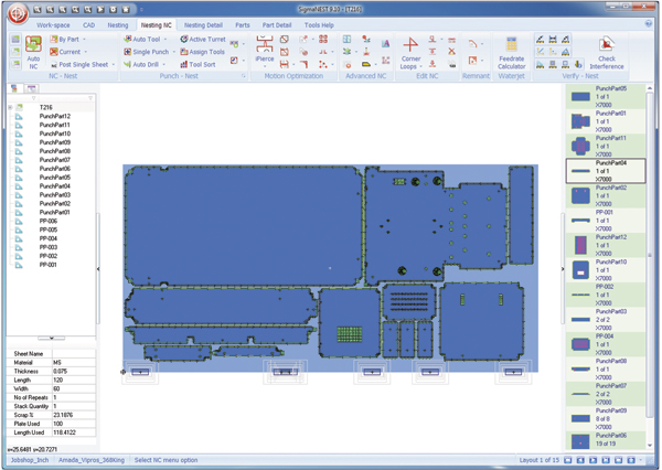
 |
| Fabricators should implement standards for creating the geometry of formed features such as louvers and embosses in a 2D CAD file, to ensure the features are handled by the nesting software. |
However, CAD data is not als perfect. How, then, can a fabricator guarantee reliable and accurate part information? The answer: Good engineering standards. We recommend that standards be attained by requiring the engineering staff to follow a well-defined set of rules for layers and methods of creating clean and consistent drawings.
Before moving on to CAD data, however, we need to first focus on inventory. Inventory records found in the MRP system must match the data in the nesting system in order to gain full advantage of the integration. Then, with the system properly set up and as material arrives at the plant and is entered into the MRP system, the inventory will automatically appear in the nesting system. As the material is consumed and remnants are created, the MRP system automatically receives those updates without manual intervention. Otherwise, the nesting system and the business system can result in a mess.
The CAD File
Regardless of where the CAD file originates—a vendor or the internal engineering department—it is important to use good engineering practices. This may require working with the engineering department creating the CAD file to agree on and maintain good engineering practices. DXF files should follow sound drafting rules, including how title blocks, dimension and other information breaks down into layer information. Because DXF files typically are 2D CAD files, they should include text strings to pull material type, thickness and other information from the file. In addition, fabricators should implement standards for creating the geometry of formed features such as louvers and embosses in a 2D CAD file, to ensure the features are handled by the nesting software.
Often, solid models can be easier to use, since the design intent is captured inside the solid model. The importing configuration can be designed to have material type and thickness data pulled directly from the model upon import, and at the same time have certain features removed. In any case, maintaining consistent engineering standards will ease the import process from any CAD system, and ultimately save the company from unnecessary duplication of effort.