Procedures for Ultrasonic Thickness Gauges

December 1, 2007
0
Comments


The ultrasonic thickness gauge (UTG) serves many purposes in any factory. Examples include detection of internal corrosion in piping; rapid sorting of different thicknesses of parts; repetitive measurements for control charting; and thickness measurements in locations not reachable by traditional micrometers. In the press shop, the UTG now measures thickness strain as an alternative to applying and measuring circle grids. These applications are reviewed in the October/November 2004 MetalForming Science of Forming columns.

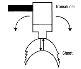
Using a UTG for accurate thickness-strain measurements requires a higher-level of detail during the measurement procedures. The UTG measures total travel time between the transducer sending the ultrasonic wave through the sheet and the transducer receiving the return wave bounced back from the back edge of the sheet (Fig. 1). For defect detection, the return wave bounces back from internal discontinuities within the sheetmetal.

 
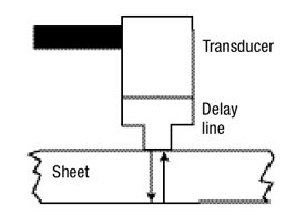
Fig. 1—Schematic showing the transducer and delay-line components of the probe for the ultrasonic thickness gauge.
The same transducer sends the outbound transmission wave and receives the inbound reflected wave. For thin sheetmetal, the time of this round trip is too short to allow the electronics within the UTG to switch from transmit to receive. To accomplish this, a delay line (often made from plastic) inserted between the transducer and the sheetmetal provides an extra time delay for both transmission and reception waves. The transducer, delay line, wave frequency and other parameters of the UTG determine whether the UTG can measure the required thickness strains. For example, a 0.020 in. thick sheet subjected to a 50 percent thinning strain would thin to 0.010 in. The UTG must be capable of measuring at least this lowest level of reduced thickness.

The plastic delay line requires daily maintenance. First, remove the delay line from the transducer and clean both transducer and delay line interface surfaces. Then check the surface of the delay line that contacts the sheetmetal. It must be flat and free of nicks and scratches. Spare delay lines should be available to replace damaged ones. Before re-assembly, completely cover the transducer-delay line interface with excess couplant. A dry interface is the primary cause of inconsistent thickness measurements.

The key cause of incorrect thickness readings is incorrect calibration. The UTG computes sheet thickness by multiplying the duration of the pulse travel by the velocity of the pulse through the sheetmetal. To calibrate the UTG, the velocity calibration dial is increased or decreased until the thickness display shows the correct value for a sheet of known thickness. Two problems can occur. If the UTG displays the sheet thickness to four decimal places, measurement of the actual sheet thickness used for calibration also must be accurate to four decimal places.

 
Fig. 2—Measuring sheetmetal formed to small radii requires greater attention to detail, especially the rocking of the probe to obtain the lowest stable thickness reading.
For calibration, any piece of sheetmetal will not provide the correct thinning strain. The composition, micro-structure, grain size, precipitates and all other characteristics of the workpiece will affect the velocity of the sound wave. Zinc and other coatings on the surface have a different velocity through the coating compared to the substrate. Therefore, good calibration requires a sample of the same material used for evaluating thinning strains. The test blank prior to deformation, the next blank, offal from the part, or a sample taken from the same lift are good calibration samples. The standard two- or three-step riser block accompanying the UTG is not suitable for good calibration for thickness strain measurement.

Measuring the thickness of a flat sheet for calibration is relatively easy. The key is the presence of a layer of couplant between the measurement probe and the sheet. This ensures a good sonic coupling between the probe and sheet.

In contrast, measuring radii requires extra precautions (Fig. 2). First, a smaller-diameter transducer allows for measurement of smaller radii of curvature. If the diameter of the probe (transducer or delay line) is too large, the couplant cannot fill the air gap. Second, a couplant of increased viscosity usually is required to retain the couplant in the gap between probe and sheetmetal. Some petroleum gels work well here. Third, rock the probe back and forth in the direction of curvature to obtain the lowest stable thickness value, then remove the probe and repeat the measurement. Two identical readings provide some measure of repeatability. Fourth, anticipate what the approximate thickness values should be. In measuring radii, double thickness values can occur when the transducer does not detect the first reflected wave and the second reflected wave stops the timer.

Many press-shop applications exist for UTG. Measurements are fast, simple and accurate compared to other available techniques. The reduced size and weight of several handheld models make them ideal for transport from one location to another. With minimum training, the UTG can become your most powerful tool for press-shop measurement and analysis. MF

Industry-Related Terms: Blank, Circle, Curvature, Edge, Forming, Gauge, Layer, Lines, Substrate, Surface, Thickness, Ultrasonic, Viscosity
View Glossary of Metalforming Terms

Technologies: Bending

Comments

Must be logged in to post a comment.
There are no comments posted.

Subscribe to the Newsletter

Start receiving newsletters.