Dimensional Consistency and Strain Gradients
November 1, 2007Comments
Localization of deformation causes gradients in surface strain (stretch), and sheet thinning. The severity of these gradients can range from slight to severe (Fig. 1). With continued deformation, these gradients become more severe and are nearly impossible to erase. Locally the material work hardens, increasing the yield strength. In addition, the constancy of volume rule says the local 50-percent increase in length of line requires a compensating flow of material into the area of increased stretch. Material must flow from a direction perpendicular to the 50-percent-strain direction and/or by a local increase in thinning.
Historically these strain gradients were associated only with torn stampings. The peak strain value would increase sufficiently to cause the onset of a local neck and subsequent fracture. When troubleshooting these failures, the presence of the strain gradient became obvious. Today, forming-limit curves are preventive tools that predict the maximum allowable major-minor strain combinations for many metal alloys. This allows part designers, tool designers, virtual metalforming operators, and others to keep strain levels below a safety margin.
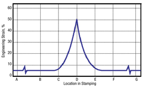
A major concern for press shops today is dimensional stability. Strain gradients are a leading contributor to dimensional instability of stampings. Assume a stamping has the strain distribution shown in Fig. 2. Most of the stamping (A, B, E and F) has a 5-percent major strain, which is the direction with the largest positive surface strain. The peak major strain of 50 percent means the deformation rate at location D is 10 times greater than in the rest of the stamping. A design feature of the stamping (sharp character line, tight bend radius) or a tooling flaw (chamfer bottom, nontangential transition from a radius to flat surface) could create the high value of strain and increased deformation rate. Plane strain mode means that no material flows into the deformation zone from the perpendicular (minor strain) direction. For constancy of volume with a plane strain mode, locations A, B, E and F would have an engineering thickness strain of -4.8 percent and location D would have a thickness strain of -33 percent.
The majority of the stamping has 3D strain values of 5 by 0 by -4.8 percent. The values for the strain gradient at location D are 50 by 0 by -33 percent. Location D has substantially more cold work and work hardening compared to the rest of the stamping. Work hardening raises the flow stress of the material, where the flow stress is the initial yield stress plus the increase in yield stress due to the cold work. The elastic stress for each location within a stamping is proportional to the flow stress. For the stamping in Fig. 2, this difference in flow stress leads to a large elastic stress gradient. The stress gradient combined with the thickness notch is a recipe for increased springback. However, springback-compensation techniques attempt to bring the stamping back to part print. Unfortunately, any elastic stresses unrelieved by springback remain in the stamping as residual or trapped stresses. These residual stresses create yet another set of dimensional problems as the stamping undergoes changes from line dies into the final part.
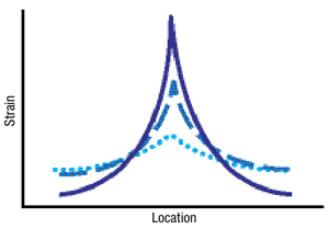
Fig. 1—Strain gradients can range from slight (dotted line) to severe (solid line). The increasing peak strain work hardens the sheetmetal and increases the elastic stress gradient.