
Page 94 - MetalForming October 2017
P. 94
Tooling by Design
By Peter Ulintz
Deep Drawing Box Shells
12
12
34
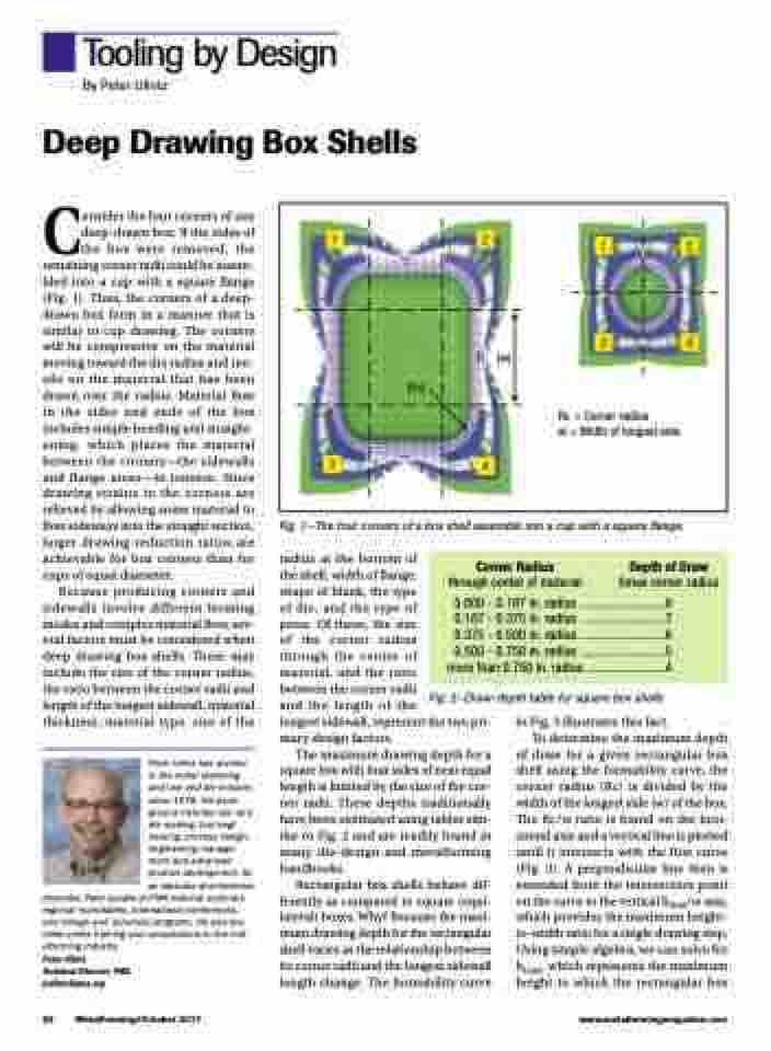
Rc = Corner radius
w = Width of longest side
(Rc)
(w)
3
4
Consider the four corners of any deep-drawn box: If the sides of the box were removed, the remaining corner radii could be assem- bled into a cup with a square flange (Fig. 1). Thus, the corners of a deep- drawn box form in a manner that is similar to cup drawing. The corners will be compressive on the material moving toward the die radius and ten- sile on the material that has been drawn over the radius. Material flow in the sides and ends of the box includes simple bending and straight- ening, which places the material between the corners—the sidewalls and flange areas—in tension. Since drawing strains in the corners are relieved by allowing some material to flow sideways into the straight section, larger drawing-reduction ratios are achievable for box corners than for cups of equal diameter.
Because producing corners and sidewalls involve different forming modes and complex material flow, sev- eral factors must be considered when deep drawing box shells. These may include the size of the corner radius, the ratio between the corner radii and length of the longest sidewall, material thickness, material type, size of the
Peter Ulintz has worked in the metal stamping and tool and die industry since 1978. His back- ground includes tool and die making, tool engi- neering, process design, engineering manage- ment and advanced product development. As an educator and technical
presenter, Peter speaks at PMA national seminars, regional roundtables, international conferences, and college and university programs. He also pro- vides onsite training and consultations to the met- alforming industry.
Peter Ulintz
Technical Director, PMA pulintz@pma.org
Fig. 1—The four corners of a box shell assemble into a cup with a square flange.
radius at the bottom of
the shell, width of flange,
shape of blank, the type
of die, and the type of
press. Of these, the size
of the corner radius
through the center of
material, and the ratio
between the corner radii
and the length of the
longest sidewall, represent the two pri- mary design factors.
The maximum drawing depth for a square box with four sides of near equal length is limited by the size of the cor- ner radii. These depths traditionally have been estimated using tables sim- ilar to Fig. 2 and are readily found in many die-design and metalforming handbooks.
Rectangular box shells behave dif- ferently as compared to square (equi- lateral) boxes. Why? Because the maxi- mum drawing depth for the rectangular shell varies as the relationship between its corner radii and the longest sidewall length change. The formability curve
Corner Radius Depth of Draw
through center of material times corner radius
0.000 - 0.187 in. radius ..........................8 0.187 - 0.375 in. radius ..........................7 0.375 - 0.500 in. radius ..........................6 0.500 - 0.750 in. radius ..........................5
more than 0.750 in. radius ........................4
Fig. 2—Draw-depth table for square box shells
in Fig. 3 illustrates this fact.
To determine the maximum depth
of draw for a given rectangular box shell using the formability curve, the corner radius (Rc) is divided by the width of the longest side (w) of the box. The Rc/w ratio is found on the hori- zontal axis and a vertical line is plotted until it intersects with the first curve (Fig. 3). A perpendicular line then is extended from the intersection point on the curve to the vertical hmax/w axis, which provides the maximum height- to-width ratio for a single drawing step. Using simple algebra, we can solve for hmax, which represents the maximum height to which the rectangular box
92 MetalForming/October 2017
www.metalformingmagazine.com
