
Page 96 - MetalForming October 2017
P. 96
94 MetalForming/October 2017
www.metalformingmagazine.com
Booth A5191
.com
may be safely drawn in one forming operation.
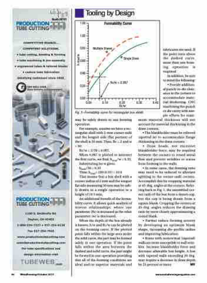
For example, assume we have a rec- tangular shell with 2-mm corner radii and the longest side (flat portion) of theshellis30mm.Thus,Rc=2andw = 30:
Rc/w = 2/30 = 0.067,
When 0.067 is plotted to intersect the first curve, we find: hmax/w = 0.35,
Substituting for w gives:
hmax/30 = 0.35
Thus: hmax= (30)(0.35) = 10.5
That means that a box shell with a
corner radius of 2 mm and the longest flat side measuring 30 mm may be safe- ly drawn in a single operation to a height of 10.5 mm.
An additional benefit of the forma- bility curve: It allows quick analysis of inverse relationships, where one parameter (Rc) is increased as the other parameter (w) is decreased.
When the depth of the box already is known, h/w and Rc/w can be plotted on the forming curve. If the plotted point falls within the large area under the solid curve, the part may be formed safely in one operation. If the point falls within the area between the dashed and solid curve, the part might be formed in one operation providing that all of the forming conditions are ideal and/or superior materials and
1.20
Formability Curve
1.00
0.80
0.60
0.40
0.20
0.00
Multiple Draws
lubricants are used. If the point rests above the dashed curve, more than one form- ing operation is required.
Tooling by Design
h-max/w
0.00
Rc/w = 0.067
0.10 0.20 0.30 Rc/w
0.40
Fig. 3—Formability curve for rectangular box shells
Single Draw
In addition, be sure to mind the following: • Provide addition- al punch-to-die clear- ance in the corners to accommodate mate- rial thickening. CNC machining the punch or die cavity with sim- ple offsets for maxi- mum material thickness will not account for material thickening in the
draw corners.
• The blankholder must be relieved
(spotted in) to accommodate flange thickening in the draw corners.
• Draw beads, not excessive blankholder force, may be required between the corners to retard metal flow and prevent wrinkles or waves from forming in the walls.
• In some cases, the drawing ratio may need to be reduced to alleviate splitting in the corner-radii corners. Accomplish this by cropping material at 45-deg. angles at the corners. Refer- ring back to Fig. 1, the assembled cor- ner radii of the box form a drawn cup, but the cup is being drawn from a square blank. Cropping the corners at 45-deg. angles reduces the drawing ratio by more closely approximating a round blank.
• Further reduce forming severity by developing an optimum blank shape, increasing die-profile radius and improving lubrication.
• Boxes with nonvertical (tapered) walls are more susceptible to wall wrin- kles. Increase blankholder force and decrease allowable box height. A box with tapered walls exceeding 20 deg. may require a decrease in draw depth by 25 percent or more. MF
