
Page 50 - MetalForming September 2017
P. 50
Tooling by Design
By Peter Ulintz
The Anatomy of a Deep-Drawn Cup
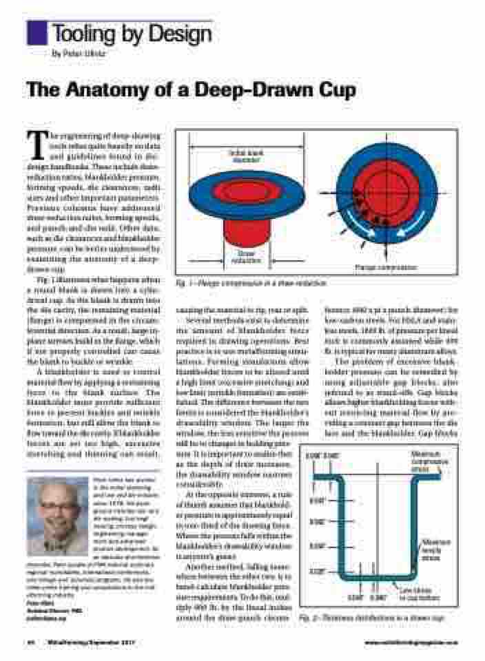
Initial blank diameter
Draw reduction
Flange compression
The engineering of deep-drawing tools relies quite heavily on data and guidelines found in die- design handbooks. These include draw- reduction ratios, blankholder pressure, forming speeds, die clearances, radii sizes and other important parameters. Previous columns have addressed draw-reduction ratios, forming speeds, and punch-and-die radii. Other data, such as die clearances and blankholder pressure, can be better understood by examining the anatomy of a deep- drawn cup.
Fig. 1 illustrates what happens when a round blank is drawn into a cylin- drical cup. As the blank is drawn into the die cavity, the remaining material (flange) is compressed in the circum- ferential direction. As a result, large in- plane stresses build in the flange, which if not properly controlled can cause the blank to buckle or wrinkle.
A blankholder is used to control material flow by applying a restraining force to the blank surface. The blankholder must provide sufficient force to prevent buckles and wrinkle formation, but still allow the blank to flow toward the die cavity. If blankholder forces are set too high, excessive stretching and thinning can result,
Peter Ulintz has worked in the metal stamping and tool and die industry since 1978. His back- ground includes tool and die making, tool engi- neering, process design, engineering manage- ment and advanced product development. As an educator and technical
presenter, Peter speaks at PMA national seminars, regional roundtables, international conferences, and college and university programs. He also pro- vides onsite training and consultations to the met- alforming industry.
Peter Ulintz
Technical Director, PMA pulintz@pma.org
Fig. 1—Flange compression in a draw reduction.
causing the material to rip, tear or split. Several methods exist to determine the amount of blankholder force required in drawing operations. Best practice is to use metalforming simu- lations. Forming simulations allow blankholder forces to be altered until a high limit (excessive stretching) and low limit (wrinkle formation) are estab- lished. The difference between the two limits is considered the blankholder’s drawability window. The larger the window, the less sensitive the process
will be to changes in holding pres- sure. It is important to realize that as the depth of draw increases, the drawability window narrows considerably.
At the opposite extreme, a rule of thumb assumes that blankhold- er pressure is approximately equal to one-third of the drawing force. Where the process falls within the blankholder’s drawability window is anyone’s guess.
Another method, falling some- where between the other two, is to hand-calculate blankholder pres- sure requirements. To do this, mul- tiply 600 lb. by the lineal inches around the draw-punch circum-
ference (600 x pi x punch diameter) for low-carbon steels. For HSLA and stain- less steels, 1800 lb. of pressure per lineal inch is commonly assumed while 400 lb. is typical for many aluminum alloys.
The problem of excessive blank- holder pressure can be remedied by using adjustable gap blocks, also referred to as stand-offs. Gap blocks allows higher blankholding forces with- out restricting material flow by pro- viding a constant gap between the die face and the blankholder. Gap blocks
0.046" 0.045"
0.043" 0.042"
0.040" 0.035"
Maximum compressive stress
Maximum tensile stress
Low stress
in cup bottom
0.040" 0.040"
48 MetalForming/September 2017
www.metalformingmagazine.com
Fig. 2—Thickness distributions in a drawn cup.
