
Page 51 - MetalForming September 2017
P. 51
Tooling by Design
Drawing clearance
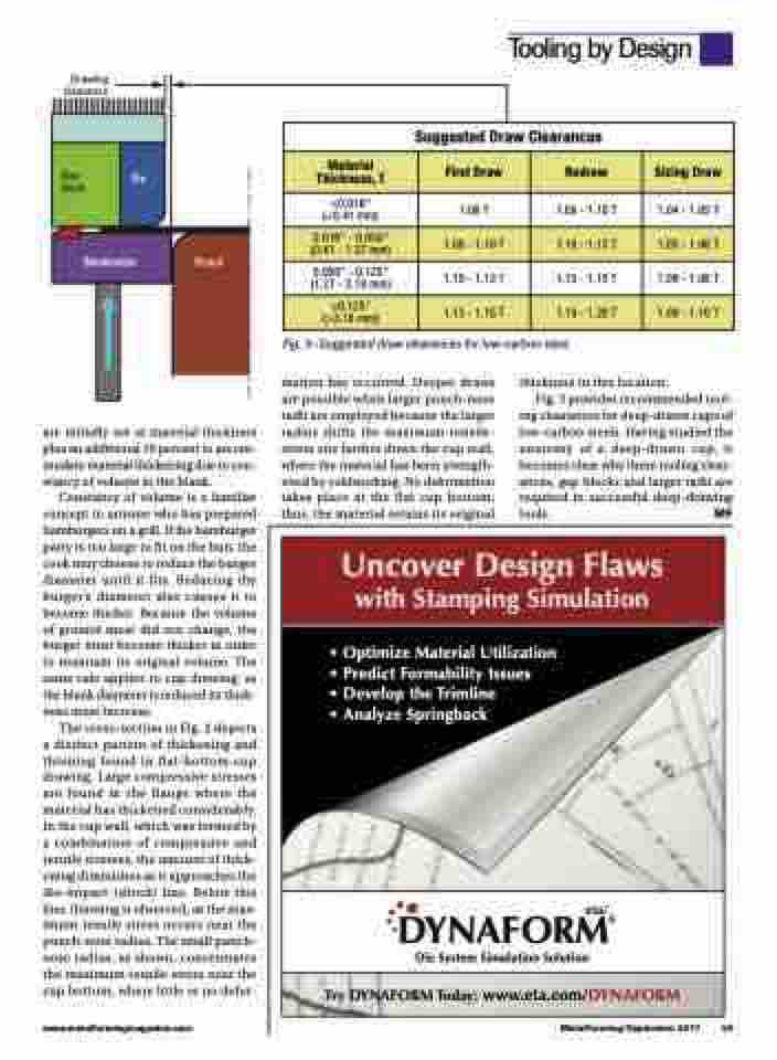
<0.016" (<0.41 mm)
0.016" - 0.050" (0.41 - 1.27 mm)
0.050" - 0.125" (1.27 - 3.18 mm)
>0.125" (>3.18 mm)
Suggested Draw Clearances
Material Thickness, T
First Draw
1.08 T
1.08 - 1.10 T
1.10 - 1.13 T
1.13 - 1.15 T
Redraw
1.09 - 1.10 T
1.10 - 1.13 T
1.13 - 1.15 T
1.15 - 1.20 T
Sizing Draw
1.04 - 1.05 T
1.05 - 1.06 T
1.06 - 1.08 T
1.08 - 1.10 T
Gap block
Die
Blankholder
Punch
are initially set at material thickness plus an additional 10 percent to accom- modate material thickening due to con- stancy of volume in the blank.
Constancy of volume is a familiar concept to anyone who has prepared hamburgers on a grill. If the hamburger patty is too large to fit on the bun, the cook may choose to reduce the burger diameter until it fits. Reducing the burger’s diameter also causes it to become thicker. Because the volume of ground meat did not change, the burger must become thicker in order to maintain its original volume. The same rule applies to cup drawing; as the blank diameter is reduced its thick- ness must increase.
The cross-section in Fig. 2 depicts a distinct pattern of thickening and thinning found in flat-bottom-cup drawing. Large compressive stresses are found in the flange where the material has thickened considerably. In the cup wall, which was formed by a combination of compressive and tensile stresses, the amount of thick- ening diminishes as it approaches the die-impact (shock) line. Below this line, thinning is observed, as the max- imum tensile stress occurs near the punch-nose radius. The small punch- nose radius, as shown, concentrates the maximum tensile stress near the cup bottom, where little or no defor-
mation has occurred. Deeper draws are possible when larger punch-nose radii are employed because the larger radius shifts the maximum-tensile- stress site farther down the cup wall, where the material has been strength- ened by coldworking. No deformation takes place at the flat cup bottom; thus, the material retains its original
thickness in this location.
Fig. 3 provides recommended tool-
ing clearances for deep-drawn cups of low-carbon steels. Having studied the anatomy of a deep-drawn cup, it becomes clear why these tooling clear- ances, gap blocks and larger radii are required in successful deep-drawing tools. MF
Fig. 3—Suggested draw clearances for low-carbon steel.
Uncover Design Flaws with Stamping Simulation
� Optimize Material Utilization � Predict Formability Issues
� Develop the Trimline
� Analyze Springback
DYNAFORM® Die System Simulation Solution
eta/
Try DYNAFORM Today: www.eta.com/DYNAFORM
www.metalformingmagazine.com
MetalForming/September 2017 49
