
Page 32 - MetalForming December 2015
P. 32
Understanding Sensors
& Error-Proofing, Part 1:
Inductive Proximity Sensors
Hundreds, if not thousands, of metalforming companies, tool- makers and pressroom per- sonnel have tried and failed to proper- ly implement electronic sensors within their dies. The sensors are consequently deemed by many to be ineffective, too delicate, impossible to properly align with a target, unable to survive the harsh environments within a die, etc. But in great measure, these failures are due to simple misunderstandings regarding sensor location, mounting and protection. We must correct these misunderstandings to ensure ideal sen- sor performance.
Toolmakers worth their salt quickly acknowledge the precision with which tooling components are engineered, designed and located within dies, from manually fed, single-stroke types on through to automatic progressive and transfer dies. Every internal component has been carefully designed and placed with precision by toolmakers, and maintained with equal care by main- tenance toolmakers during production cycles. Should not the same care be taken regarding selection and installa- tion of electronic sensors to protect these valuable electronic investments?
Where is it written that it is okay to crash and repair a die? What genius came up with the phrase, “Oh, that die can take a bad hit?” Who designs dies to
George Keremedjiev is president of Tec- know Education Services, Inc., Boze- man, MT; 406/587-4751, www.mfgad- vice.com.
This first in a series of articles will address the basic topics of how to properly select, install and protect inductive proximity sensors within tooling.
BY GEORGE KEREMEDJIEV
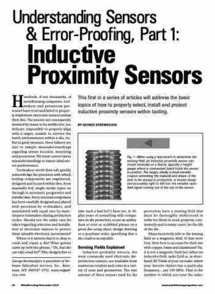
Fig. 1—When using a test bench to determine the sensing field, an inductive proximity sensor can mount vertically on a fixture, typically a height gauge where a customized insert holds the sensor in position. The target, ideally a small metallic coupon mimicking the material and shape of the item to be sensed in production, is moved slowly and accurately right to left into the invisible radio- field signal coming out of the top of the sensor.
take such a bad hit? I have yet, in 30- plus years of consulting with compa- nies on die protection, to see an adden- dum or note or scribbled phrase on a given die-setup sheet, design drawing or a purchase order, specifying that a die crash is acceptable.
Sensing Fields Explained
Inductive proximity sensors, the most commonly used electronic die- protection sensors, are available from numerous vendors and come in a vari- ety of sizes and geometries. The vast amount of these sensors used for die
protection have a sensing field that must be thoroughly understood in order for them to work properly, con- sistently and in many cases, for the life of the die.
Many incorrectly refer to the sensing field as a magnetic field. If that were true, then how to account for their use with copper, brass and aluminum? No, it is not a magnetic field but rather an inductive field, radio field or, in short- hand,RF.Thinkofyourcarradio,where your favorite station has a particular frequency...say 100 MHz. That is the number to which you tune the radio.
30 MetalForming/December 2015
www.metalformingmagazine.com
