
Page 33 - MetalForming December 2015
P. 33
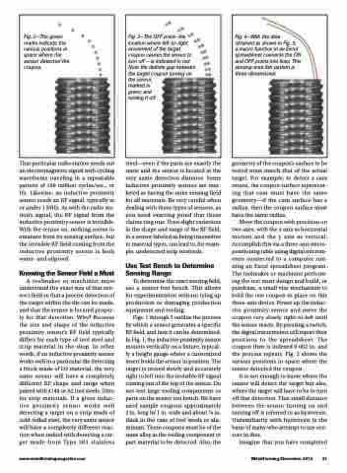
 Fig. 2—The green marks indicate the various positions in space where the sensor detected the coupon.
 Fig. 3—The OFF point—the location where left-to-right movement of the target coupon causes the sensor to turn off − is indicated in red. Note the definite gap between the target coupon turning on the sensor,
marked in green, and turning it off.
 Fig. 4—With the data
obtained as shown in Fig. 3,
a macro function in an Excel spreadsheet connects the ON and OFF points into lines. This sensing-area fish pattern is three-dimensional.
That particular radio station sends out an electromagnetic signal with cycling waveforms traveling in a repeatable pattern of 100 million cycles/sec., or Hz. Likewise, an inductive proximity sensor sends an RF signal, typically at or under 1 MHz. As with the radio sta- tion’s signal, the RF signal from the inductive proximity sensor is invisible. With the sensor on, nothing seems to emanate from its sensing surface, but the invisible RF field coming from the inductive proximity sensor is both water- and oilproof.
Knowing the Sensor Field a Must
A toolmaker or machinist must understand the exact size of that sen- sor’s field so that a precise detection of the target within the die can be made, and that the sensor is located proper- ly for that detection. Why? Because the size and shape of the inductive proximity sensor’s RF field typically differs for each type of tool steel and strip material in the shop. In other words, if an inductive proximity sensor works well in a particular die detecting a block made of D2 material, the very same sensor will have a completely different RF shape and range when paired with 4140 or A2 tool steels. Ditto for strip materials. If a given induc- tive proximity sensor works well detecting a target on a strip made of cold-rolled steel, the very same sensor will have a completely different reac- tion when tasked with detecting a tar- get made from Type 303 stainless
steel—even if the parts are exactly the same and the sensor is located at the very same detection distance. Some inductive proximity sensors are mar- keted as having the same sensing field for all materials. Be very careful when dealing with these types of sensors, as you need exacting proof that these claims ring true. Even slight variations in the shape and range of the RF field, in a sensor labeled as being insensitive to material types, can lead to, for exam- ple, undetected strip misfeeds.
Use Test Bench to Determine Sensing Range
To determine the exact sensing field, use a sensor test bench. This allows for experimentation without tying up production or damaging production equipment and tooling.
Figs. 1 through 5 outline the process by which a sensor generates a specific RF field, and how it can be determined. In Fig. 1, the inductive proximity sensor mounts vertically on a fixture, typical- ly a height gauge where a customized insert holds the sensor in position. The target is moved slowly and accurately right to left into the invisible RF signal coming out of the top of the sensor. Do not test large tooling components or parts on the sensor test bench. We have used sample coupons approximately 2 in. long by 1 in. wide and about 1⁄8 in. thick in the case of tool steels or alu- minum. These coupons must be of the same alloy as the tooling component or part material to be detected. Also, the
geometry of the coupon’s surface to be tested must match that of the actual target. For example, to detect a cam return, the coupon surface represent- ing that cam must have the same geometry—if the cam surface has a radius, then the coupon surface must have the same radius.
Move the coupon with precision on two axes, with the x axis as horizontal motion and the y axis as vertical. Accomplish this via a three-axis micro- positioning table using digital microm- eters connected to a computer run- ning an Excel spreadsheet program. The toolmaker or machinist perform- ing the test must design and build, or purchase, a small vise mechanism to hold the test coupon in place on this three-axis device. Power up the induc- tive proximity sensor and move the coupon very slowly right-to-left until the sensor reacts. By pressing a switch, the digital micrometers will report their positions to the spreadsheet. The coupon then is indexed 0.002 in. and the process repeats. Fig. 2 shows the various positions in space where the sensor detected the coupon.
It is not enough to know where the sensor will detect the target but also, where the target will have to be to turn off that detection. That small distance between the sensor turning on and turning off is referred to as hysteresis. Unfamiliarity with hysteresis is the bane of many who attempt to use sen- sors in dies.
Imagine that you have completed
www.metalformingmagazine.com
MetalForming/December 2015 31
