
Page 34 - MetalForming December 2015
P. 34
Inductive Proximity Sensors
There are many factors that affect how well your stampings run.
Choosing the best lubricant is a very important one.
Make sure you’re getting the best advice.
the testing as described above and know exactly, to 0.001 in., where the sensor must be to detect the target within the die. But wait—the target has a slight natural vibration to it. It could be the end of the strip where a short feed will be detected but the strip is unstable and vibrating a few thou- sands of an inch. Perhaps it is simply vibrating a little in sympathy with the vibration of the press. In any case, it is conceivable that the natural move- ment of the target can cause the sensor to first turn on and then off. This, in turn, can cause nuisance stops and create upheaval in the pressroom, per- haps to the extent that the “stupid sen- sor” is turned off completely. What to do? How much target movement is acceptable to the sensor being test- ed? Enter hysteresis.
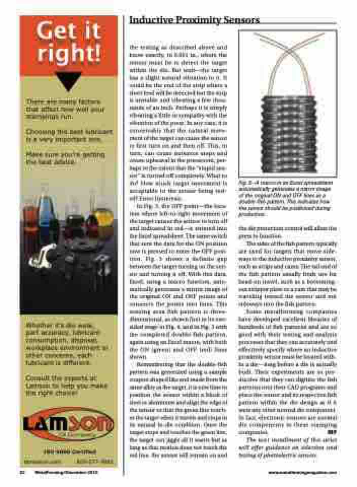
In Fig. 3, the OFF point—the loca- tion where left-to-right movement of the target causes the sensor to turn off and indicated in red—is entered into the Excel spreadsheet. The same switch that sent the data for the ON position now is pressed to enter the OFF posi- tion. Fig. 3 shows a definite gap between the target turning on the sen- sor and turning it off. With this data, Excel, using a macro function, auto- matically generates a mirror image of the original ON and OFF points and connects the points into lines. This sensing area fish pattern is three- dimensional, as shown first in its one- sided stage in Fig. 4, and in Fig. 5 with the completed double-fish pattern, again using an Excel macro, with both the ON (green) and OFF (red) lines shown.
Remembering that the double-fish pattern was generated using a sample coupon shaped like and made from the same alloy as the target, it is now time to position the sensor within a block of steel or aluminum and align the edge of the sensor so that the green line touch- es the target when it travels and stops in its natural in-die condition. Once the target stops and touches the green line, the target can jiggle all it wants but as long as that motion does not touch the red line, the sensor will remain on and
Whether it’s die wear, part accuracy, lubricant consumption, disposal, workplace environment or other concerns, each lubricant is different.
Consult the experts at Lamson to help you make the right choice!
Fig. 5—A macro in an Excel spreadsheet automatically generates a mirror image of the original ON and OFF lines as a double-fish pattern. This indicates how the sensor should be positioned during production.
the die protection control will allow the press to function.
The sides of the fish pattern typically are used for targets that move side- ways to the inductive proximity sensor, such as strips and cams. The tail end of the fish pattern usually finds use for head-on travel, such as a bottoming- out stripper plate or a cam that may be traveling toward the sensor and not sideways into the fish pattern.
Some metalforming companies have developed excellent libraries of hundreds of fish patterns and are so good with their testing and analysis processes that they can accurately and effectively specify where an inductive proximity sensor must be located with- in a die—long before a die is actually built. Their experiments are so pro- ductive that they can digitize the fish patterns into their CAD programs and place the sensor and its respective fish pattern within the die design as if it were any other normal die component. In fact, electronic sensors are normal die components in these stamping companies. MF
The next installment of this series will offer guidance on selection and testing of photoelectric sensors.
lamsonoil.com
800-577-7895
32 MetalForming/December 2015
www.metalformingmagazine.com
