
Page 32 - MetalForming July 2015
P. 32
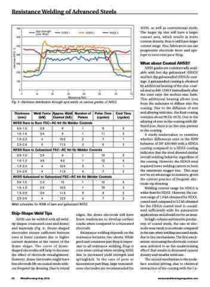
Resistance Welding of Advanced Steels
   700 600 500 400 300 200 100
0
0 10 20 30 40 50 60 70
Measuring Point
High Strength (Low Alloy)
AHSS 1 AHSS 2 AHSS 3
                    Fig. 3—Hardness distribution through spot welds on various grades of AHSS.
AHSS, as well as conventional steels. The larger tip size will have a larger contact area, which results in lower current density, thus it will have larger current range. Also, fabricators can use progressive electrode force and ups- lope to overcome poor fitup.
What about Coated AHSS?
AHSS grades are commercially avail- able with hot-dip galvanized (HDGI) and hot-dip galvanealled (HDGA) coat- ings. A galvanealled coating is obtained by additional heating of the zinc-coat- ed steel at 840-1100 F immediately after the steel exits the molten-zinc bath. This additional heating allows iron from the substrate to diffuse into the coating. Due to the diffusion of iron and alloying with zinc, the final coating contains about 90 Zn-10 Fe. Due to the alloying of zinc in the coating with dif- fused iron, there is no free zinc present in the coating.
A study undertaken to examine whether differences exist in the RSW behavior of DP 420/800 with a HDGA coating compared to a HDGI coating indicates that the steel showed similar overall welding behavior regardless of the coating. However, the HDGA steel required lower welding current to form the minimum nugget size. This may not be an advantage in industry, given the current practice of frequent elec- trode-tip dressing.
Welding-current range for HDGA is wider than for HDGI. However, the cur- rent range of 1.6 kA obtained for HDGI- coated steel compared to 2.2 kA obtained for the HDGA-coated steel is consid- ered sufficiently wide for automotive applications and should not be an issue.
In high-volume automotive produc- tion of coated steels, the rate of elec- trode wear tends to accelerate compared to the rate when welding uncoated steels, due to two mechanisms. The first mech- anism: increasing the electrode contact area (referred to as the mushrooming effect) that results in decreased current density and smaller weld size.
The second mechanism is electrode- face erosion/pitting, due to chemical interaction of the coating with the Cu-
    Thickness (mm)
  Weld Force (kN)
 Approx. Weld Current (kA)
Number of Pulses
  Pulse Time (cycles)
Cool Time (cycles)
  AHSS Bare to Bare FSC—AC 60-Hz Welder Controls
 0.6–1.0
2.6
8
1
9
0
1.0–1.6
3.6
9
1
11
0
1.6–2.3
4
10.5
2
7
1
2.3–2.6
5
11.5
3
8
2
  AHSS Bare to Galvanized FSC—AC 60-Hz Welder Controls
 0.6–1.0
2.6
9
1
10
0
1.0–1.3
3.6
9.5
1
12
0
1.3–2.4
4
10.5
3
7
1
2.4–2.6
4
11.5
4
7
2
  AHSS Galvanized to Galvanized FSC—AC 60-Hz Welder Controls
 0.6–1.0
2.3
10
1
14
0
1.0–1.3
2.6
10.5
1
16
0
1.3–2.0
3.6
11.5
3
8
2
2.0–2.6
4
12.5
4
7
2
                                     Weld schedules for RSW of bare and galvanized AHSS.
Ship-Shape Weld Tips
AHSS can be welded with all weld- tip shapes (truncated cone and dome) and materials (Fig. 4). Dome-shaped electrodes ensure sufficient buttons even at lower currents due to higher current densities at the center of the dome shape. The curve of dome- shaped electrodes will help to decrease the effect of electrode misalignment. However, dome electrodes might have less electrode life on coated steels with- out frequent tip dressing. Due to round
edges, the dome electrode will have fewer tendencies to develop surface cracks when compared to a truncated electrode.
Resistance welding depends on the resistance between two sheets. While good and consistent part fitup is impor- tant to all resistance welding, fitup is even more critical when welding AHSS due to increased yield strength and springback. In the case of poor or inconsistent part fitup, large truncated- cone electrodes are recommended for
30 MetalForming/July 2015
www.metalformingmagazine.com
Hardness (HV0, 1)
