
Page 31 - MetalForming July 2015
P. 31
5.0 4.5 4.0 3.5 3.0 2.5 2.0
0 0.5
1.0 1.5
Welding Current Range (kA)
3.0 3.5
2.0 2.5
360 340 320 300 280 260 240 220 200
0 0.5 1.0
Welding Current Range (kA)
1.5 2.0 2.5
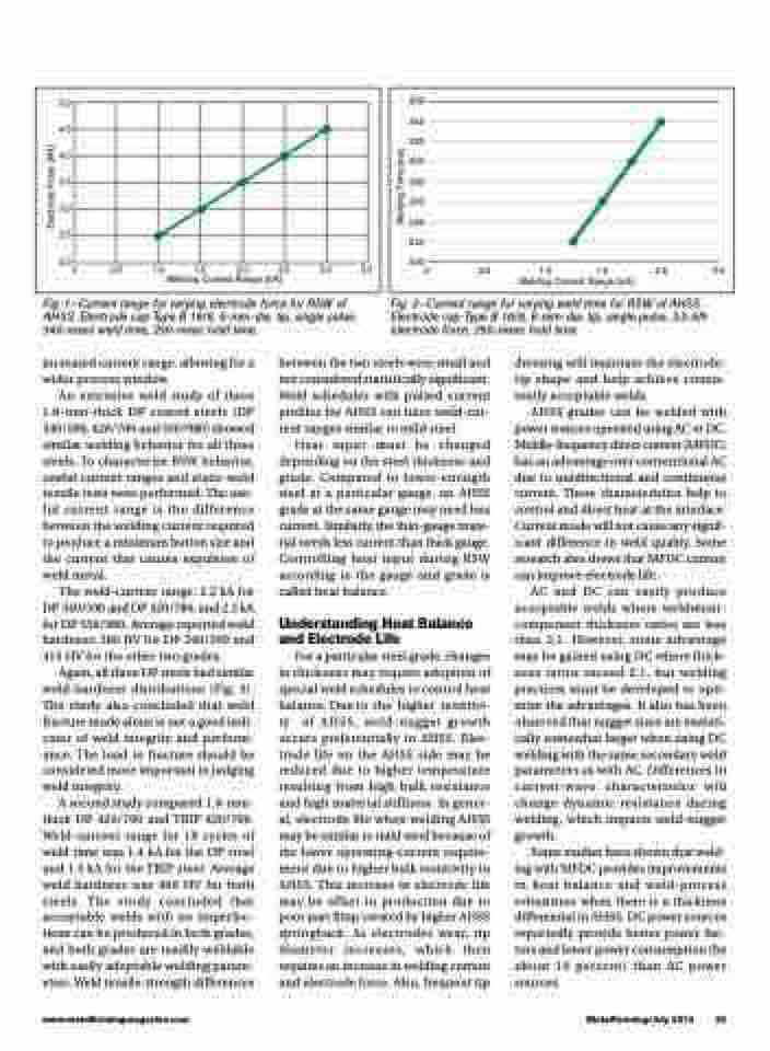
Fig. 1—Current range for varying electrode force for RSW of AHSS. Electrode cap Type B 16/6, 6-mm-dia. tip, single pulse, 340-msec weld time, 250-msec hold time.
Fig. 2—Current range for varying weld time for RSW of AHSS. Electrode cap Type B 16/6, 6-mm-dia. tip, single pulse, 3.5-kN electrode force, 250-msec hold time.
increased current range, allowing for a wider process window.
An extensive weld study of three 1.6-mm-thick DP coated steels (DP 340/590, 420/780 and 550/980) showed similar welding behavior for all three steels. To characterize RSW behavior, useful current ranges and static-weld tensile tests were performed. The use- ful current range is the difference between the welding current required to produce a minimum button size and the current that causes expulsion of weld metal.
The weld-current range: 2.2 kA for DP 340/590 and DP 420/780, and 2.5 kA for DP 550/980. Average reported weld hardness: 380 HV for DP 340/590 and 415 HV for the other two grades.
Again, all three DP steels had similar weld-hardness distributions (Fig. 3). The study also concluded that weld fracture mode alone is not a good indi- cator of weld integrity and perform- ance. The load to fracture should be considered more important in judging weld integrity.
A second study compared 1.6-mm- thick DP 420/700 and TRIP 420/700. Weld-current range for 18 cycles of weld time was 1.4 kA for the DP steel and 1.5 kA for the TRIP steel. Average weld hardness was 400 HV for both steels. The study concluded that acceptable welds with no imperfec- tions can be produced in both grades, and both grades are readily weldable with easily adoptable welding param- eters. Weld tensile-strength differences
between the two steels were small and not considered statistically significant. Weld schedules with pulsed current profiles for AHSS can have weld-cur- rent ranges similar to mild steel.
Heat input must be changed depending on the steel thickness and grade. Compared to lower-strength steel at a particular gauge, an AHSS grade at the same gauge may need less current. Similarly, the thin-gauge mate- rial needs less current than thick gauge. Controlling heat input during RSW according to the gauge and grade is called heat balance.
Understanding Heat Balance and Electrode Life
For a particular steel grade, changes in thickness may require adoption of special weld schedules to control heat balance. Due to the higher resistivi- ty of AHSS, weld-nugget growth occurs preferentially in AHSS. Elec- trode life on the AHSS side may be reduced due to higher temperature resulting from high bulk resistance and high material stiffness. In gener- al, electrode life when welding AHSS may be similar to mild steel because of the lower operating-current require- ment due to higher bulk resistivity in AHSS. This increase in electrode life may be offset in production due to poor part fitup created by higher AHSS springback. As electrodes wear, tip diameter increases, which then requires an increase in welding current and electrode force. Also, frequent tip
dressing will maintain the electrode- tip shape and help achieve consis- tently acceptable welds.
AHSS grades can be welded with power sources operated using AC or DC. Middle-frequency direct current (MFDC) has an advantage over conventional AC due to unidirectional and continuous current. These characteristics help to control and direct heat at the interface. Current mode will not cause any signif- icant difference in weld quality. Some research also shows that MFDC current can improve electrode life.
AC and DC can easily produce acceptable welds where weldment- component thickness ratios are less than 2:1. However, some advantage may be gained using DC where thick- ness ratios exceed 2:1, but welding practices must be developed to opti- mize the advantages. It also has been observed that nugget sizes are statisti- cally somewhat larger when using DC welding with the same secondary weld parameters as with AC. Differences in current-wave characteristics will change dynamic resistance during welding, which impacts weld-nugget growth.
Some studies have shown that weld- ing with MFDC provides improvements in heat balance and weld-process robustness when there is a thickness differential in AHSS. DC power sources reportedly provide better power fac- tors and lower power consumption (by about 10 percent) than AC power sources.
www.metalformingmagazine.com
MetalForming/July 2015 29
Electrode Force (kN)
Welding Time (ms)
