
Page 30 - MetalForming July 2015
P. 30
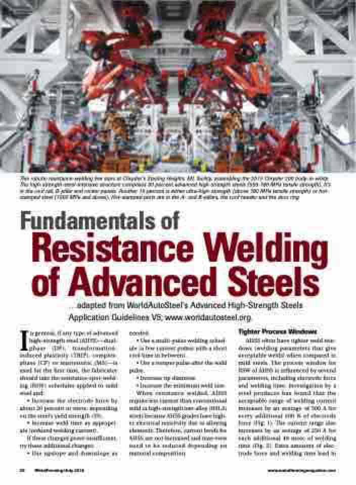
 This robotic resistance-welding line stars at Chrysler’s Sterling Heights, MI, facility, assembling the 2015 Chrysler 200 body-in-white. The high-strength-steel-intensive structure comprises 30 percent advanced high-strength steels (550-780 MPa tensile strength). It’s in the roof rail, B-pillar and rocker panels. Another 10 percent is either ultra-high-strength (above 780 MPa tensile strength) or hot- stamped steel (1000 MPa and above). Hot-stamped parts are in the A- and B-pillars, the roof header and the door ring.
Fundamentals of
Resistance Welding
of Advanced Steels
...adapted from WorldAutoSteel’s Advanced High-Strength Steels Application Guidelines V5; www.worldautosteel.org.
In general, if any type of advanced high-strength steel (AHSS)—dual- phase (DP), transformation- induced plasticity ( TRIP), complex- phase (CP) or martensitic (MS)—is used for the first time, the fabricator should take the resistance-spot-weld- ing (RSW ) schedules applied to mild steel and:
• Increase the electrode force by about 20 percent or more, depending on the steel’s yield strength (YS).
• Increase weld time as appropri- ate (reduced welding current).
If these changes prove insufficient, try these additional changes:
• Use upslope and downslope as
needed.
• Use a multi-pulse welding sched-
ule (a few current pulses with a short cool time in between).
• Use a temper pulse after the weld pulse.
• Increase tip diameter.
• Increase the minimum weld size. When resistance welded, AHSS
require less current than conventional mild or high-strength low-alloy (HSLA) steels because AHSS grades have high- er electrical resistivity due to alloying elements. Therefore, current levels for AHSS are not increased and may even need to be reduced depending on material composition.
Tighter Process Windows
AHSS often have tighter weld win- dows (welding parameters that give acceptable welds) when compared to mild steels. The process window for RSW of AHSS is influenced by several parameters, including electrode force and welding time. Investigation by a steel producer has found that the acceptable range of welding current increases by an average of 500 A for every additional 500 N of electrode force (Fig. 1). The current range also increases by an average of 250 A for each additional 40 msec of welding time (Fig. 2). Extra amounts of elec- trode force and welding time lead to
28 MetalForming/July 2015
www.metalformingmagazine.com
