
Page 33 - MetalForming July 2015
P. 33
9 8 7 6 5 4 3 2
6.0
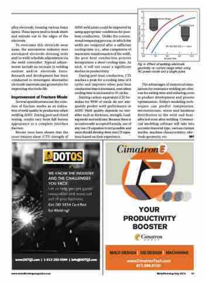
Dome Shape
Button Size (mm)
alloy electrode, forming various brass layers. These layers tend to break down and extrude out to the edges of the electrode.
To overcome this electrode-wear issue, the automotive industry uses automated electrode-dressing tools and/or weld-schedule adjustments via the weld controller. Typical adjust- ments include an increase in welding current and/or electrode force. Research and development has been conducted to investigate alternative electrode materials and geometries for improving electrode life.
Improvement of Fracture Mode
Several specifications use the crite- rion of fracture modes as an indica- tion of weld quality in production when welding AHSS. During peel and chisel testing, results vary from full button appearance to a complete interface fracture.
Recent tests have shown that the cross-tension shear (CTS) strength of
AHSS weld joints could be improved by using appropriate conditions for post- heat conduction. Unlike the conven- tional tempering process, in which the welds are tempered after a sufficient cooling time (i.e., after completion of martensite transformation of the weld), the post-heat conduction process incorporates a short cooling time. As such, it will not cause a significant decline in productivity.
During post-heat conduction, CTS reaches a peak for a cooling time of 6 cycles and improves when post-heat conduction time is increased, even when cooling time is increased to 35 cycles.
Existing carbon-equivalent (CE) for- mulas for RSW of steels do not ade- quately predict weld performance in AHSS. Weld quality depends on vari- ables such as thickness, strength, load- ing mode and weld size. Because there is no universally accepted formula, use of any one CE equation is not possible and users should develop their own CE equa- tions based on their experience.
Truncated Cone
DP 350/600 CR, t = 1.4mm
7.0 8.0 9.0 10.0 Current (kA)
Fig. 4—Effect of welding-electrode geometry on current range when using AC power mode and a single pulse.
The advantages of numerical simu- lations for resistance welding are obvi- ous for saving time and reducing costs in product development and process optimization. Today’s modeling tech- niques can predict temperature, microstructure, stress and hardness distribution in the weld and heat- affected zone after welding. Commer- cial modeling software will take into account material type, various current modes, machine characteristics, elec- trode geometry, etc. MF
WE KNOW THE INDUSTRY AND THE CHALLENGES YOU FACE.
��� �� ���� ��� ��� ������ ����������� ��� ���� ��� ��� �� ���� ���������
��� ��� ���� �������� ��� ��������
www.DOTQS.com | 1-312-285-5344 | info@DOTQS.com
YOUR PRODUCTIVITY BOOSTER
MOLDDESIGN| DIEDESIGN| MACHINING www.CimatronTech.com
877.596.9700
www.metalformingmagazine.com
MetalForming/July 2015 31
