
Page 39 - MetalForming December 2014
P. 39
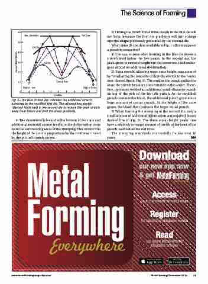
   Fig. 2—The blue dotted line indicates the additional stretch achieved by the modified first die. This allowed less stretch (dashed black line) in the second die to reduce the peak stretch away from failure and limit the sharp gradients.
4) The sheetmetal is locked at the bottom of the cone and additional material cannot feed into the deformation zone from the surrounding areas of the stamping. This means that the height of the cone is proportional to the total area created by the plotted stretch curves.
5) Having the punch travel more deeply in the first die will not help, because the first die gradients will just enlarge into the shape previously generated by the second die.
What clues do the data available in Fig. 1 offer to support a possible correction?
1) The center zone after forming in the first die shows a stretch level below the two peaks. In the second die, the peaks grow to extreme height but the center zone still under- goes almost no additional deformation.
2) Extra stretch, allowing more cone height, was created by transferring the majority of first-die stretch to the center area (dotted line in Fig. 2). The smaller the punch radius the more the stretch becomes concentrated in the center. There- fore, operators welded an additional small-diameter punch on top of the pole of the first die punch. As the modified punch contacts the blank, the additional punch generates a large amount of center stretch. As the height of the cone grows, the blank then contacts the larger initial punch.
3) When forming the stamping in the second die, only a small amount of additional deformation was required (heavy dashed line in Fig. 2). The three equal-height peaks now have a relatively constant amount of stretch at the head of the punch, well below the red zone.
The stamping was made successfully for the next 10 years. MF
Download
our new app now & get
Access
up to the minute industry news
Register
for upcoming magazine events
Read
the latest MetalForming magazine articles
The Science of Forming
 60
50
40
30
20
10
0
 Max. Allowable
2nd Die
Edge of Cone
Fail Zone
               1st Die
       Conical Pole
 Edge of Cone
         Location
                                                                                                                  www.metalformingmagazine.com
MetalForming/December 2014 37
Percent, Major Stretch
