
Page 38 - MetalForming December 2014
P. 38
The Science of Forming
By Stuart Keeler
Solutions Without Data? Simply Guesses
60
50
40
30
20
10
0
Max. Allowable
2nd Die
Edge of Cone
Fail Zone
1st Die
Conical Pole
Edge of Cone
Location
Often we hear employees in the pressroom say things like, “I solved an identical problem 12 years ago, by adding double draw beads on the opposite side of the binder from the tear.” Take that statement and analyze it log- ically. Each stamping has a large number (50 or more) of inter- acting inputs that determine the exact parameters of the final part. Even if a few measurements (data) were made, most like- ly they no longer are available for comparison.
Also, how many measurements were made of the inputs to the stamping having the current problem? Probably only a few. Therefore, using the suggested correction used on the 12-yr.-old stamping rarely will correct the current prob- lem, and may make it worse.
Opinions without data are simply guesses. Solutions are procedures designed to solve a problem—a final corrective action. Before even suggesting a solution, we first must identify the causes of the problem. In many problem-solving meetings, team leaders will list the likely problem sources on a white board, and the team will vote to select those to be moved up to the solution stage. Hopefully they have the problem part in the room with them, providing data to fuel the discussion.
In a press shop, the stampings house the data because they undergo the interaction of the inputs, and summarize the results in the stamping as it exits the press. To obtain the data, one must converse with the stamping, asking it questions that can be answered by surveying the data.
May sound ridiculous, but I do it every time I encounter a problematic stamped part. I etch a small-diameter circle- grid pattern on the blank and, after forming, measure the amount, direction and gradient of stretch. I highlight high stretch areas and plot the stretch patterns on the forming- limit diagram (FLD) to determine the severity of the defor- mation in those areas. Red indicates probable failure, yellow shows where sufficient stretch failure may occur with changes of inputs, and green indicates acceptable stamping. In some cases, ultrasonic thickness gauges can provide a quick check.
Stuart Keeler (Keeler Technologies LLC) is known worldwide for his discovery of forming limit diagrams, development of circle-grid analysis and implementa- tion of other press-shop analysis tools. Keeler’s metal- forming experience includes 24 years at National Steel Corporation and 12 years at The Budd Company Technical Center, enabling him to bring a very diverse background to this column and to the seminars he teaches for PMA.
Keeler Technologies LLC
P.O. Box 283 | Grosse Ile, MI 48138 Fax: 734/671-2271 keeltech@comcast.net
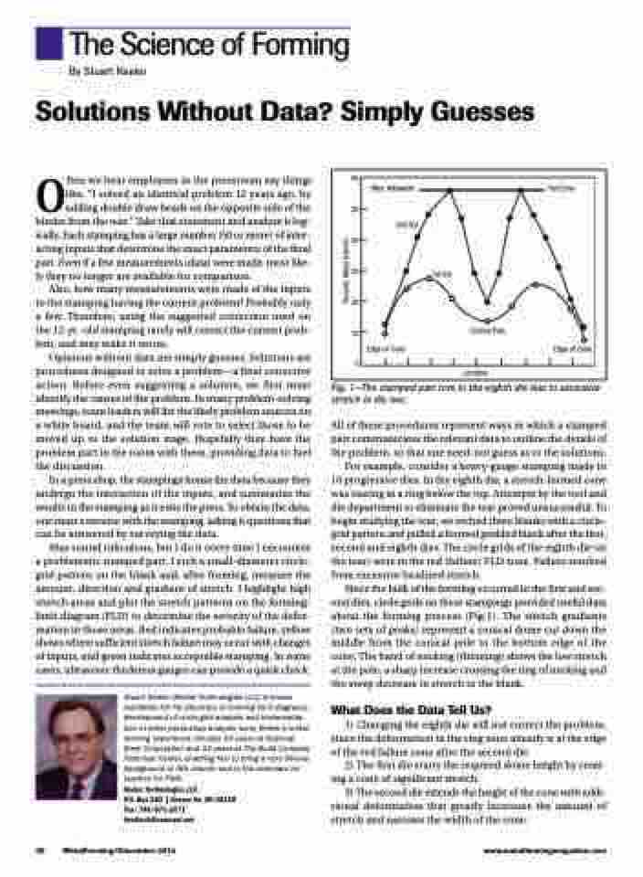
Fig. 1—The stamped part tore in the eighth die due to excessive stretch in die two.
All of these procedures represent ways in which a stamped part communicates the relevant data to outline the details of the problem, so that one need-not guess as to the solutions.
For example, consider a heavy-gauge stamping made in 10 progressive dies. In the eighth die, a stretch-formed cone was tearing in a ring below the top. Attempts by the tool and die department to eliminate the tear proved unsuccessful. To begin studying the tear, we etched three blanks with a circle- grid pattern and pulled a formed gridded blank after the first, second and eighth dies. The circle grids of the eighth die (at the tear) were in the red (failure) FLD zone. Failure resulted from excessive localized stretch.
Since the bulk of the forming occurred in the first and sec- ond dies, circle grids on these stampings provided useful data about the forming process (Fig.1). The stretch gradients (two sets of peaks) represent a conical dome cut down the middle from the conical pole to the bottom edge of the cone. The band of necking (thinning) shows the low stretch at the pole, a sharp increase crossing the ring of necking and the steep decrease in stretch to the blank.
What Does the Data Tell Us?
1) Changing the eighth die will not correct the problem, since the deformation in the ring zone already is at the edge of the red failure zone after the second die.
2) The first die starts the required dome height by creat- ing a cone of significant stretch.
3) The second die extends the height of the cone with addi- tional deformation that greatly increases the amount of stretch and narrows the width of the cone.
36 MetalForming/December 2014
www.metalformingmagazine.com
Percent, Major Stretch
