
Page 68 - MetalForming August 2014
P. 68
Tooling by Design
By Peter Ulintz
Progressive Dies and Tipping Moments
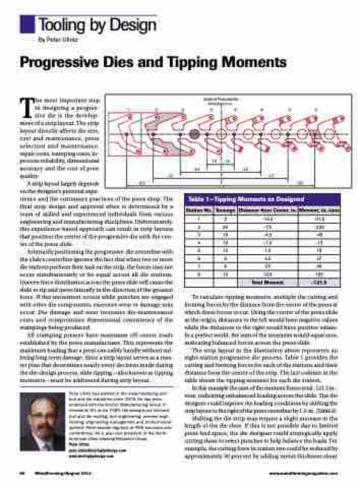
Center of Press and Die (dimensions in in.)
➀➁➂➃➄➅➆➇
-7.5
-4.5
-1.5
-1.5
-4.5
-7.5
-10.5
-10.5
The most important step in designing a progres- sive die is the develop- ment of a strip layout. The strip layout directly affects die size, cost and maintenance, press selection and maintenance, repair costs, stamping costs, in- process reliability, dimensional accuracy and the cost of poor quality.
A strip layout largely depends
on the designer’s personal expe-
rience and the customary practices of the press shop. The final strip design and approval often is determined by a team of skilled and experienced individuals from various engineering and manufacturing disciplines. Unfortunately, this experience-based approach can result in strip layouts that position the center of the progressive die with the cen- ter of the press slide.
Arbitrarily positioning the progressive-die centerline with the slide’s centerline ignores the fact that when two or more die stations perform their task on the strip, the forces may not occur simultaneously or be equal across all die stations. Uneven force distribution across the press slide will cause the slide to tip and move laterally in the direction of the greatest force. If this movement occurs while punches are engaged with other die components, excessive wear or damage may occur. Die damage and wear increases die-maintenance costs and compromises dimensional consistency of the stampings being produced.
All stamping presses have maximum off-center loads established by the press manufacturer. This represents the maximum loading that a press can safely handle without suf- fering long-term damage. Since a strip layout serves as a mas- ter plan that determines nearly every decision made during the die-design process, slide tipping—also known as tipping moments—must be addressed during strip layout.
Peter Ulintz has worked in the metal stamping and tool and die industries since 1978. He has been employed with the Anchor Manufacturing Group in Cleveland, OH, since 1989. His background includes tool and die making, tool engineering, process engi- neering, engineering management and product devel- opment. Peter speaks regularly at PMA seminars and conferences. He is also vice president of the North American Deep Drawing Research Group.
Peter Ulintz pete.ulintz@toolingbydesign.com www.toolingbydesign.com
To calculate tipping moments, multiply the cutting and forming forces by the distance from the center of the press at which these forces occur. Using the center of the press slide as the origin, distances to the left would have negative values while the distances to the right would have positive values. In a perfect world, the sum of the moments would equal zero, indicating balanced forces across the press slide.
The strip layout in the illustration above represents an eight-station progressive-die process. Table 1 provides the cutting and forming forces for each of the stations and their distance from the center of the strip. The last column in the table shows the tipping moment for each die station.
In this example the sum of the moment forces total -121.5 in.- tons, indicating unbalanced loading across the slide. The die designer could improve the loading conditions by shifting the strip layout to the right of the press centerline by 1.5-in. (Table 2).
Shifting the die strip may require a slight increase in the length of the die shoe. If this is not possible due to limited press-bed space, the die designer could strategically apply cutting shear to select punches to help balance the loads. For example, the cutting force in station two could be reduced by approximately 50 percent by adding metal-thickness shear
Table 1—Tipping Moments as Designed
Station No.
Tonnage
Distance from Center, in.
Moment, in.-tons
1
3
-10.5
-31.5
2
30
-7.5
-225
3
10
-4.5
-45
4
10
-1.5
-15
5
12
1.5
18
6
6
4.5
27
7
6
7.5
45
8
10
10.5
105
Total Moment
-121.5
66 MetalForming/August 2014
www.metalformingmagazine.com
