
Page 69 - MetalForming August 2014
P. 69
Tooling by Design
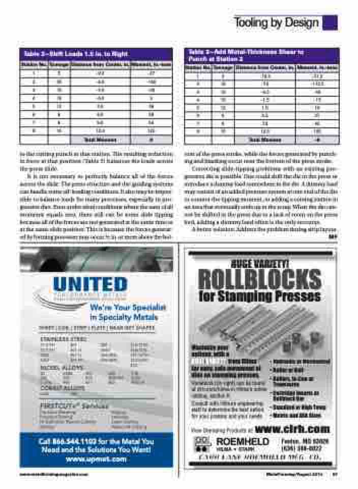
Table 2—Shift Loads 1.5 in. to Right
Station No.
Tonnage
Distance from Center, in.
Moment, in.-tons
1
3
-9.0
-27
2
30
-6.0
-180
3
10
-3.0
-30
4
10
-0.0
0
5
12
3.0
36
6
6
6.0
36
7
6
9.0
54
8
10
12.0
120
Total Moment
9
Table 3—Add Metal-Thickness Shear to Punch at Station 2
Station No.
Tonnage
Distance from Center, in.
Moment, in.-tons
1
3
-10.5
-31.5
2
15
-7.5
-112.5
3
10
-4.5
-45
4
10
-1.5
-15
5
12
1.5
18
6
6
4.5
27
7
6
7.5
45
8
10
10.5
105
Total Moment
-9
to the cutting punch in that station. The resulting reduction in force at that position (Table 3) balances the loads across the press slide.
It is not necessary to perfectly balance all of the forces across the slide. The press structure and die-guiding systems can handle some off-loading conditions. It also may be impos- sible to balance loads for many processes, especially in pro- gressive dies. Even under ideal conditions where the sum of all moments equals zero, there still can be some slide tipping because all of the forces are not generated at the same time or at the same slide position. This is because the forces generat- ed by forming processes may occur 1⁄2 in. or more above the bot-
We’re Your Specialist
in Specialty Metals
SHEET | COIL | STRIP | PLATE | NEAR NET SHAPES STAINLESS STEEL
tom of the press stroke, while the forces generated by punch- ing and blanking occur near the bottom of the press stroke.
Correcting slide-tipping problems with an existing pro- gressive die is possible. One could shift the die in the press or introduce a dummy load somewhere in the die. A dummy load may consist of an added pressure system at one end of the die to counter the tipping moment, or adding a coining station in an area that eventually ends up in the scrap. When the die can- not be shifted in the press due to a lack of room on the press bed, adding a dummy load often is the only recourse.
A better solution: Address the problem during strip layout.
MF
HUGE VARIETY! ROLLBLOCKS
for Stamping Presses
Maximize your
options, with a
HUGE VARIETY from Hilma
for easy, safe movement of dies on stamping presses. Variations (on right) can be found atclrh.com/hilmainHilma’sonline catalog, section K.
Consult with Hilma’s engineering staff to determine the best option for your presses and your needs.
�
H
�
al
H
y
yd
d
r
r
a
au
u
l
l
i
ic
co
o
r
rM
M
e
e
c
c
h
h
a
a
n
n
i
i
c
c
a
View Stamping Products at: www.clrh.com
Fenton, MO 63026 (636) 386-8022
� Roller or Ball
� Rollers, In-Line or Transverse
�CartridgeInsertsor Rollblock Bar
� Standard or High Temp � Metric and ASA Sizes
17-4 PH 17-7 PH 2205 2507
301 301 1⁄4 301 1⁄2 301 FH
302 304H 304/304L 309/309S
310/310S 316/316L 321/321H 347/347H 410
718 X750 Alloy X
NICKEL ALLOYS
20 A286 263 330 C-276 400
COBALT ALLOYS
L605 188
600 601 617
625 800H/HT 825
FIRSTCUT+® Services
Precision Shearing
Precision Sawing Hi-Definition Plasma Cutting Slitting
Edging
Leveling
Laser Cutting Water Jet Cutting
Call 866.544.1103 for the Metal You Need and the Solutions You Want! www.upmet.com
www.metalformingmagazine.com
MetalForming/August 2014 67
