
Page 66 - MetalForming August 2014
P. 66
The Science of Forming By Stuart Keeler
Material Strengths are Increasing, are You Prepared?—Part 2
Rigid Rigid
Start of neck Deepening of neck Fracture
Most activities in the world are constrained by the laws of nature, including metalform- ing. One must pay some type of price to receive a specific benefit. Last month’s column described how higher materi- al strength generates higher elastic stresses and an increase in springback. Correcting springback to maintain print dimensional specifications becomes more difficult and expensive. Even worse, residual or trapped elastic stresses also can increase and cause reductions in the stability and robustness of stamp- ing dimensions during subsequent pro- cessing or in-service operations.
Another important parameter for metalforming is the material’s capaci-
ty to workharden
during deforma-
tion. Measurement
of this property
started in the early
1900s when the pri-
mary press-shop
tool was a hardness
tester. Materials
become harder
when deformed.
We now know that
changes in strength
control stretch distribution, not hard- ness. The correct term actually should be work strengthening. The rate of strengthening per unit of deformation is defined as the workhardening expo-
Fig. 2—The failure site of a stamping is a through-thickness (local) neck that deforms while the remainder of the stamping is rigid. A circle measuring the stretch at the start of the neck becomes a data point on the forming limit curve.
0.3
0.2
0.1
0
0 50 100 Yield strength (Ksi)
Average
Greatest stress concentration
Stamping Location
Fig. 1—A stretch gradient grows at a site of concentrated stress. The final height of the gradient is controlled by the workhardening exponent—n-value.
nent (n-value). For increased stretcha- bility one desires greater workharden- ing—a higher n- value. That may sound backwards—a material that gets stronger faster will stretch more. Two examples will clarify what takes place dur- ing metalforming.
Stuart Keeler (Keeler Technologies LLC) is known worldwide for his discovery of forming limit diagrams, development of circle-grid analysis and implementation of other press-shop analysis
tools. Keeler’s metalform- ing experience includes 24 years at National
Steel Corporation and 12 years at The Budd Com- pany Technical Center, enabling him to bring a very diverse background to this column and to the sem- inars he teaches for PMA.
Keeler Technologies LLC P.O. Box 283
Grosse Ile, MI 48138 Fax: 734/671-2271 keeltech@comcast.net
First, consider the formation of a stretch gradient, a nar- row localization of high deformation located at a zone of concentrated high stress (Fig. 1). Such locations can be character lines, tight bends, small domes or other severe features in the stamping where deformation begins. If the material did not workharden during deformation, all deformation would concentrate in the gradient as the material thinned. The sheetmetal would quickly reach maximum stretch and tear. With some workhardening (n-value above zero), deformation would cause the material in the gradi- ent to become stronger than the sur-
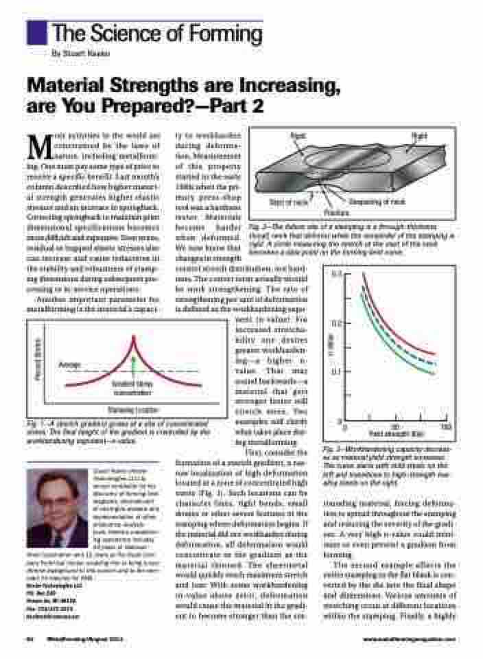
Fig. 3—Workhardening capacity decreas- es as material yield strength increases. The curve starts with mild steels on the left and transitions to high-strength low- alloy steels on the right.
rounding material, forcing deforma- tion to spread throughout the stamping and reducing the severity of the gradi- ent. A very high n-value could mini- mize or even prevent a gradient from forming.
The second example affects the entire stamping as the flat blank is con- verted by the die into the final shape and dimensions. Various amounts of stretching occur at different locations within the stamping. Finally, a highly
64 MetalForming/August 2014
www.metalformingmagazine.com
Percent Stretch
n value
