
Page 80 - MetalForming October 2013
P. 80
Tooling by Design
By Peter Ulintz
Guidelines for Punching and Cutting
Tooling Technology
2t
4t
>10t
While punching and cutting are the most common operations performed by stamping dies, stampers do not always pay close enough attention to the sequence of operations required to maintain product qual- ity and process stability. It generally is more cost effective to punch holes in a flat blank to avoid use of expensive cams and increased die complexity. However, when product design includes a hole in a vertical flange with critical location tol- erances, the process engineer may elect to punch the hole after forming operations have been completed. It may be less expensive to punch the hole in the flat, but maintaining accurate position in the final stamping might prove difficult or impossible with such an approach.
Stampers should punch holes and openings in deep- drawn parts after forming. Extensive material flow in deep- drawing operations make it very difficult to develop final hole sizes and their locations. Holes located in regions of high compression or tension will distort easily.
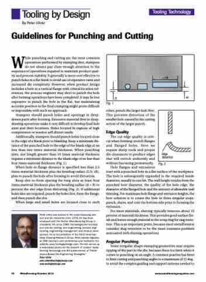
Additionally, stampers should punch holes located close to the edge of a blank prior to blanking. Keep a minimum dis- tance of the punched hole to the edge of the blank edge at no less than two times material thickness. When punching slots, slot length greater than 10 times material thickness requires a minimum distance to the blank edge of no less than four times material thickness (Fig. 1).
When hole-to-flange distance is specified less than 2.5 times material thickness plus the bending radius (2.5t +R), plan to punch the hole after forming to avoid distortion.
Keep slot-to-form spacing for long slots at least four times material thickness plus the bending radius (4t + R) to prevent the slot edge from distorting (Fig. 2). If additional holes also are required, punch the holes first, form the flange, and then punch the slot.
When large and small holes are located close to each
Peter Ulintz has worked in the metal stamping and tool and die industries since 1978. He has been employed with the Anchor Manufacturing Group in Cleveland, OH, since 1989. His background includes tool and die making, tool engineering, process engi- neering, engineering management and product devel- opment. He is vice-president of the North American Deep Drawing Research Group. Peter speaks regularly at PMA seminars and conferences and maintains the website, www.ToolingbyDesign.com. The site serves as a web-based source for the transfer of modern metal- forming technology and the advancement of “Perfor- mance-Based Die Engineering Strategies.”
Peter Ulintz pete.ulintz@toolingbydesign.com www.toolingbydesign.com
Fig. 1
other, punch the larger hole first. This prevents distortion of the smaller hole caused by the cutting action of the larger punch.
Edge Quality
The cut-edge quality is criti- cal when forming stretch flanges and flanged holes. Here we require sharp tools and proper die clearances to produce edges that will stretch uniformly and without fracturing prematurely.
Fig. 2
78
MetalForming/October 2013
www.metalformingmagazine.com
Hole flanges and extrusions
start with a punched hole in a flat surface of the workpiece. The hole is subsequently expanded to the required inside diameter, usually in one hit. The wall height results from the punched hole diameter, the quality of the hole edge, the diameter of the flanged hole and the amount of allowable wall thinning. For maximum hole flange and extrusion heights, the best solution is to create the hole in three singular steps: punch, shave, and coin the bottom side prior to forming the extrusion.
For most materials, shaving typically removes about 10 percent of material thickness. This provides good surface fin- ish and leaves enough material in the scrap ring for slug reten- tion. This is an important point, because most metalformers consider slug retention to be the most common problem associated with shaving operations.
Angular Punching
Some irregular-shape stamping geometries may require tipping of the part in the die, because there is a limit when it comes to punching on an angle. A common practice has been to limit cutting and punching angles to a maximum of 15 deg., to avoid the complex guiding and support systems needed to
Edge distortion
