
Page 35 - MetalForming December 2012
P. 35
Tooling Technology
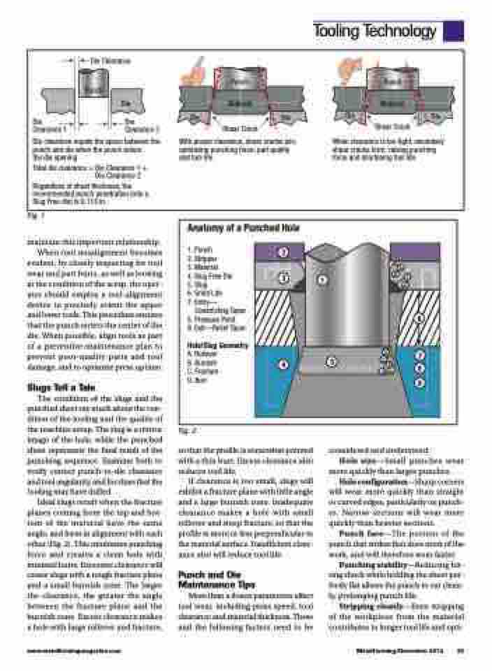
Die Clearance
Punch Punch
Punch
Die Clearance 1
Die
Die Clearance 2
Die
Material
Shear Crack
Die
Die
Material
Shear Crack
Die
Die clearance equals the space between the punch and die when the punch enters
the die opening
Total die clearance = Die Clearance 1 + Die Clearance 2
Regardless of sheet thickness, the recommended punch penetration (into a Slug Free die) is 0.118 in.
With proper clearance, shear cracks join,
optimizing punching force, part quality shear cracks form, raising punching and tool life. force and shortening tool life.
When clearance is too tight, secondary
Fig. 1
maintain this important relationship. When tool misalignment becomes evident, by closely inspecting for tool wear and part burrs, as well as looking at the condition of the scrap, the oper- ator should employ a tool-alignment device to precisely orient the upper and lower tools. This procedure ensures that the punch enters the center of the die. When possible, align tools as part of a preventive-maintenance plan to prevent poor-quality parts and tool damage, and to optimize press uptime.
Slugs Tell a Tale
The condition of the slugs and the punched sheet say much about the con- dition of the tooling and the quality of the machine setup. The slug is a mirror image of the hole, while the punched sheet represents the final result of the punching sequence. Examine both to verify correct punch-to-die clearance and tool angularity, and for clues that the tooling may have dulled.
Ideal slugs result when the fracture planes coming from the top and bot- tom of the material have the same angle, and form in alignment with each other (Fig. 2). This minimizes punching force and creates a clean hole with minimal burrs. Excessive clearance will create slugs with a rough fracture plane and a small burnish zone. The larger the clearance, the greater the angle between the fracture plane and the burnish zone. Excess clearance makes a hole with large rollover and fracture,
Fig. 2
so that the profile is somewhat pointed with a thin burr. Excess clearance also reduces tool life.
If clearance is too small, slugs will exhibit a fracture plane with little angle and a large burnish zone. Inadequate clearance makes a hole with small rollover and steep fracture, so that the profile is more or less perpendicular to the material surface. Insufficient clear- ance also will reduce tool life.
Punch and Die Maintenance Tips
More than a dozen parameters affect tool wear, including press speed, tool clearance and material thickness. These and the following factors need to be
considered and understood:
Hole size—Small punches wear
more quickly than larger punches. Hole configuration—Sharp corners will wear more quickly than straight or curved edges, particularly on punch- es. Narrow sections will wear more
quickly than heavier sections.
Punch face—The portion of the punch that strikes first does most of the
work, and will therefore wear faster. Punching stability—Reducing hit- ting shock while holding the sheet per- fectly flat allows the punch to cut clean-
ly, prolonging punch life.
Stripping cleanly—Even stripping
of the workpiece from the material contributes to longer tool life and opti-
Anatomy of a Punched Hole
1. Punch
2. Stripper
3. Material
4. Slug Free Die C
5. Slug
6. Grind Life
7. Entry—
Constricting Taper
8. Pressure Point
9. Exit—Relief Taper
Hole/Slug Geometry
A. Rollover B. Burnish C. Fracture D. Burr
2
3
1
A B
D
6
D
5C 4B
A
7 8
9
www.metalformingmagazine.com
MetalForming/December 2012 33
