
Page 32 - MetalForming December 2012
P. 32
The Science of Forming
By Stuart Keeler
Breakage Case Study—Data Prevails Over Instinct
Too often, stamping-plant workers use instinct rather than data to solve breakage problems, particularly dur- ing die tryout. To illustrate how data can lead us to the root cause of failure and provide feedback during corrective modifications, consider a case study involving stamping a backing plate for automotive drum brakes in a sequence of ten dies. Three dies (first, second and seventh) form two iden- tical embossments on the backing plate, part of the hydraulic cylinder system that actuates the brake shoes. During pro- duction, embossments began to tear in the seventh die.
ring of localized stretch developing in the dome.
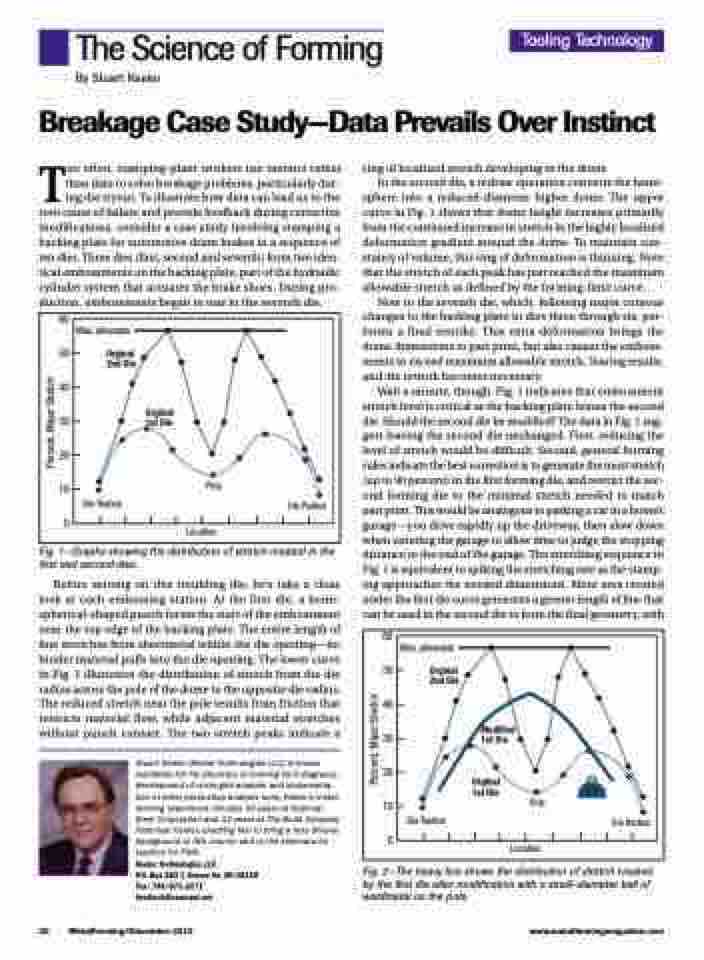
In the second die, a redraw operation converts the hemi- sphere into a reduced-diameter higher dome. The upper curve in Fig. 1 shows that dome height increases primarily from the continued increase in stretch in the highly localized deformation gradient around the dome. To maintain con- stancy of volume, this ring of deformation is thinning. Note that the stretch of each peak has just reached the maximum
allowable stretch as defined by the forming-limit curve. Now to the seventh die, which, following major contour changes to the backing plate in dies three through six, per- forms a final restrike. This extra deformation brings the dome dimensions to part print, but also causes the emboss- ments to exceed maximum allowable stretch. Tearing results,
and die rework becomes necessary.
Wait a minute, though. Fig. 1 indicates that embossment
stretch level is critical as the backing plate leaves the second die. Should the second die be modified? The data in Fig. 1 sug- gest leaving the second die unchanged. First, reducing the level of stretch would be difficult. Second, general forming rules indicate the best correction is to generate the most stretch (up to 90 percent) in the first forming die, and restrict the sec- ond forming die to the minimal stretch needed to match part print. This would be analogous to parking a car in a home’s garage—you drive rapidly up the driveway, then slow down when entering the garage to allow time to judge the stopping distance to the end of the garage. The stretching sequence in Fig. 1 is equivalent to spiking the stretching rate as the stamp- ing approaches the needed dimensions. More area created under the first die curve generates a greater length of line that can be used in the second die to form the final geometry, with
Fig. 1—Graphs showing the distribution of stretch created in the first and second dies.
Before zeroing on this troubling die, let’s take a close look at each embossing station. At the first die, a hemi- spherical-shaped punch forms the start of the embossment near the top edge of the backing plate. The entire length of line stretches from sheetmetal within the die opening—no binder material pulls into the die opening. The lower curve in Fig. 1 illustrates the distribution of stretch from the die radius across the pole of the dome to the opposite die radius. The reduced stretch near the pole results from friction that restricts material flow, while adjacent material stretches without punch contact. The two stretch peaks indicate a
Stuart Keeler (Keeler Technologies LLC) is known worldwide for his discovery of forming limit diagrams, development of circle-grid analysis and implementa- tion of other press-shop analysis tools. Keeler’s metal- forming experience includes 24 years at National Steel Corporation and 12 years at The Budd Company Technical Center, enabling him to bring a very diverse background to this column and to the seminars he teaches for PMA.
Keeler Technologies LLC
P.O. Box 283 | Grosse Ile, MI 48138 Fax: 734/671-2271 keeltech@comcast.net
Fig. 2—The heavy line shows the distribution of stretch created by the first die after modification with a small-diameter ball of weldmetal on the pole.
Tooling Technology
60
50
40
30
20
10
0
Location
Max. allowable
Orginal 2nd Die
Orginal 1st Die
Pole
Die Radius
Die Radius
60
50
40
30
20
10
0
Location
Max. allowable
Orginal 2nd Die
Die Radius
Modified 1st Die
Orginal 1st Die
Pole
Die Radius
30 MetalForming/December 2012
www.metalformingmagazine.com
Percent, Major Stretch
Percent, Major Stretch
