
Page 43 - MetalForming April 2012
P. 43
Tooling Technology
A Mechanical-Fastener Primer
Mechanically mounted threaded fasteners in automotive sheetmetal applications typically fall into three categories: self pierce and rivet, rivet forming, and pressed insert. Self-piercing fasteners incorporate a cutting edge that, together with the inser- tion tool’s bottom die, pierce a hole for the fastener to be located and riveted in posi- tion. Rivet-type nuts and
studs are inserted into pre- formed holes and have their shanks formed into a rivet head by the lower tool. Insert-type fasteners do not deform during installation, but rely on the base material flowing into undercuts and recesses in the fastener to achieve the required location and retention.
Thread sizes range from
M6 to M14. At the lower
end of this spread, applications in the automotive sector include non-structural brackets to retain trim pieces. M10 fasteners find use in medium-duty applications, while M12 parts are used in suspension and subframe assemblies.
Performance criteria include vibration and fatigue resistance. Here, welded fas- teners can suffer significant failures due to thermal disruption of the sheetmetal structure, corrosion and from weld-heat damage to coated or plated surfaces. By contrast, mechanically attached nuts and studs prove ideal for use with corrosion- resistant finishes and materials such as the galvanized steel.
Standard mechanical fasteners are available in grade 8.8 steel studs and 8 steel nuts, a full strength-grade higher than welded equivalents. In addition, they can be heattreated to grade 10.9 (or 12.9 in the case of studs), and 10 or 12 for nuts. An extensive range of mechanically attached aluminum nuts and studs also is available.
Finally, in-die fasteners are making their way into stampings of advanced high- strength steels. Examples include the insertion of class 10 RND nuts in Land-Rover Freelander 2 ‘A’ posts, which are produced from 600-MPa steel; class 12.9 studs in 850-MPa seat rails and seatbelt anchorage points in the company’s Freelander 2 and latest Discovery models; and Class 10 M8 RND nuts are inserted in 1200- MPa-steel side-impact beams used by Mercedes.
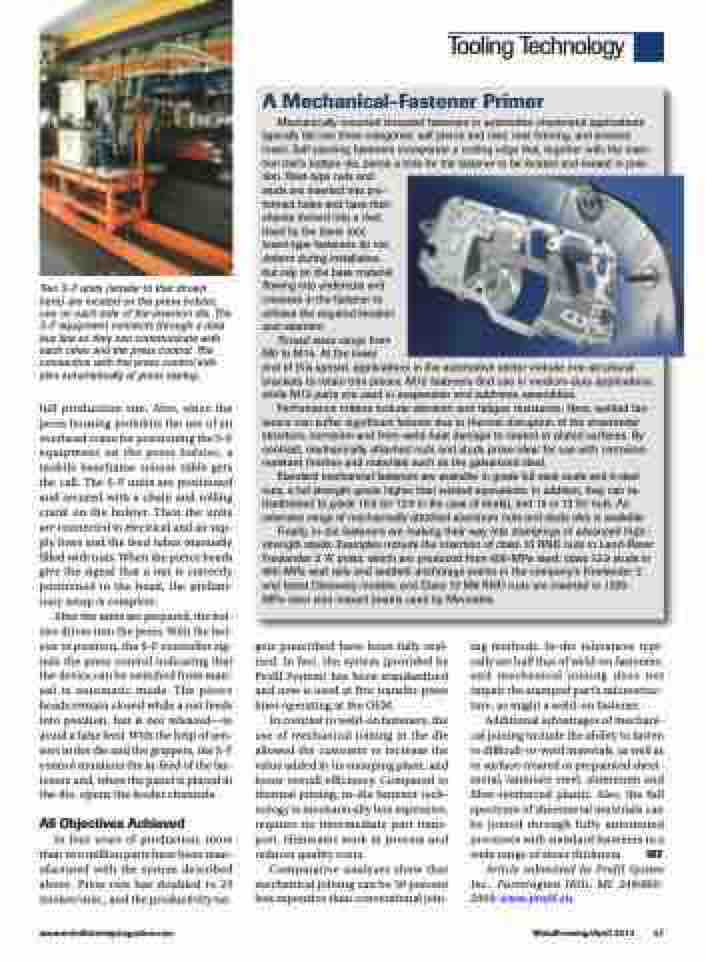
Two S-F units (similar to that shown here) are located on the press bolster, one on each side of the insertion die. The S-F equipment connects through a data bus line so they can communicate with each other and the press control. The connection with the press control initi- ates automatically at press startup.
full production run. Also, since the press housing prohibits the use of an overhead crane for positioning the S-F equipment on the press bolster, a mobile baseframe scissor table gets the call. The S-F units are positioned and secured with a chain and rolling crank on the bolster. Then the units are connected to electrical and air sup- ply lines and the feed tubes manually filled with nuts. When the pierce heads give the signal that a nut is correctly positioned in the head, the prelimi- nary setup is complete.
After the units are prepared, the bol- ster drives into the press. With the bol- ster in position, the S-F controller sig- nals the press control indicating that the device can be switched from man- ual to automatic mode. The pierce heads remain closed while a nut feeds into position, but is not released—to avoid a false feed. With the help of sen- sors in the die and the grippers, the S-F control monitors the in-feed of the fas- teners and, when the panel is placed in the die, opens the feeder channels.
All Objectives Achieved
In four years of production, more than two million parts have been man- ufactured with the system described above. Press rate has doubled to 25 strokes/min., and the productivity tar-
gets prescribed have been fully real- ized. In fact, the system (provided by Profil System) has been standardized and now is used at five transfer-press lines operating at the OEM.
In contrast to weld-on fasteners, the use of mechanical joining in the die allowed the customer to increase the value added in its stamping plant, and boost overall efficiency. Compared to thermal joining, in-die fastener tech- nology is mechanically less expensive, requires no intermediate part trans- port, eliminates work in process and reduces quality costs.
Comparative analyses show that mechanical joining can be 30 percent less expensive than conventional join-
ing methods. In-die tolerances typi- cally are half that of weld-on fasteners, and mechanical joining does not impair the stamped part’s microstruc- ture, as might a weld-on fastener.
Additional advantages of mechani- cal joining include the ability to fasten to difficult-to-weld materials, as well as to surface-treated or prepainted sheet- metal, laminate steel, aluminum and fiber-reinforced plastic. Also, the full spectrum of sheetmetal materials can be joined through fully automated processes with standard fasteners in a wide range of sheet thickness. MF
Article submitted by Profil System Inc., Farmington Hills, MI: 248/860- 2909; www.profil.eu.
www.metalformingmagazine.com
MetalForming/April 2012 41
