
Page 40 - MetalForming April 2012
P. 40
The Science of Forming By Stuart Keeler
Tooling Technology
Compressive Forming–Asset or Liability?
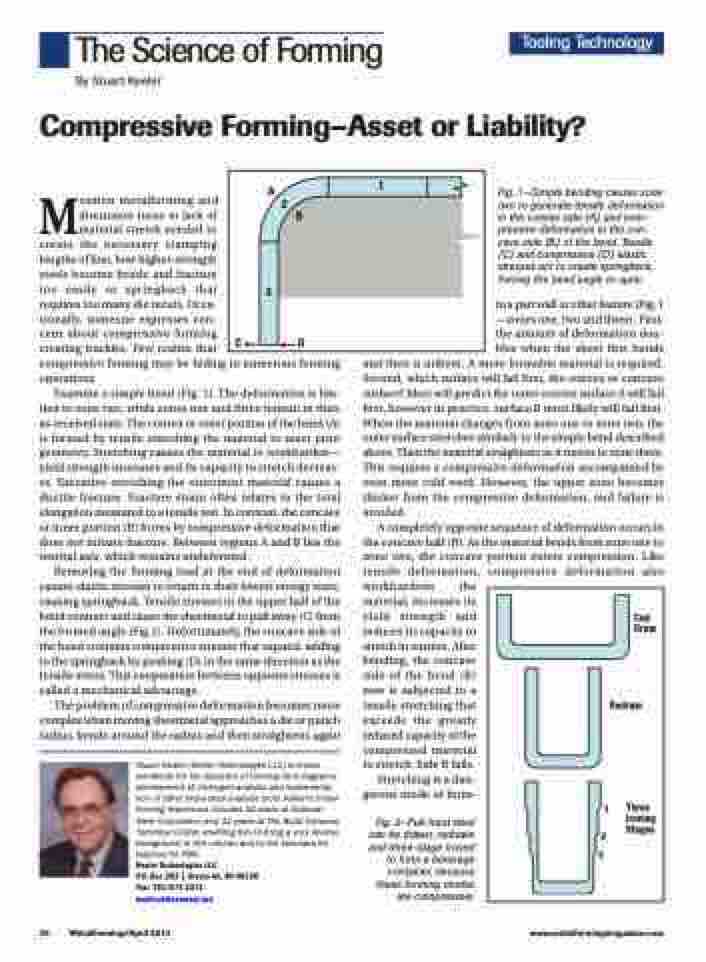
A
2
B
3
CD
1
Mention metalforming and
discussion turns to lack of
material stretch needed to
create the necessary stamping
lengths of line, how higher-strength
steels become brittle and fracture
too easily or springback that
requires too many die recuts. Occa-
sionally, someone expresses con-
cern about compressive forming
creating buckles. Few realize that
compressive forming may be hiding in numerous forming operations.
Examine a simple bend (Fig. 1). The deformation is lim- ited to zone two, while zones one and three remain in their as-received state. The convex or outer portion of the bend (A) is formed by tensile stretching the material to meet print geometry. Stretching causes the material to workharden— yield strength increases and its capacity to stretch decreas- es. Excessive stretching the outermost material causes a ductile fracture. Fracture strain often relates to the total elongation measured in a tensile test. In contrast, the concave or inner portion (B) forms by compressive deformation that does not initiate fracture. Between regions A and B lies the neutral axis, which remains undeformed.
Removing the forming load at the end of deformation causes elastic stresses to return to their lowest energy state, causing springback. Tensile stresses in the upper half of the bend contract and cause the sheetmetal to pull away (C) from the formed angle (Fig.1). Unfortunately, the concave side of the bend contains compressive stresses that expand, adding to the springback by pushing (D) in the same direction as the tensile stress. This cooperation between opposite stresses is called a mechanical advantage.
The problem of compressive deformation becomes more complex when moving sheetmetal approaches a die or punch radius, bends around the radius and then straightens again
Stuart Keeler (Keeler Technologies LLC) is known worldwide for his discovery of forming limit diagrams, development of circle-grid analysis and implementa- tion of other press-shop analysis tools. Keeler’s metal- forming experience includes 24 years at National Steel Corporation and 12 years at The Budd Company Technical Center, enabling him to bring a very diverse background to this column and to the seminars he teaches for PMA.
Keeler Technologies LLC
P.O. Box 283 | Grosse Ile, MI 48138 Fax: 734/671-2271 keeltech@comcast.net
Fig. 1—Simple bending causes zone two to generate tensile deformation in the convex side (A) and com- pressive deformation in the con- cave side (B) of the bend. Tensile (C) and compressive (D) elastic stresses act to create springback, forcing the bend angle to open.
in a part wall or other feature (Fig. 1 —zones one, two and three). First, the amount of deformation dou- bles when the sheet first bends
and then is unbent. A more formable material is required. Second, which surface will fail first, the convex or concave surface? Most will predict the outer convex surface A will fail first, however in practice, surface B most likely will fail first. When the material changes from zone one to zone two, the outer surface stretches similarly to the simple bend described above. Then the material straightens as it moves to zone three. This requires a compressive deformation accompanied by even more cold work. However, the upper zone becomes thicker from the compressive deformation, and failure is avoided.
A completely opposite sequence of deformation occurs in the concave half (B). As the material bends from zone one to zone two, the concave portion enters compression. Like tensile deformation, compressive deformation also workhardens the
material, increases its
yield strength and
reduces its capacity to
stretch in tension. After
bending, the concave
side of the bend (B)
now is subjected to a
tensile stretching that
exceeds the greatly
reduced capacity of the
compressed material
to stretch. Side B fails.
Stretching is a dan- gerous mode of form-
Fig. 2—Full-hard steel can be drawn, redrawn and three-stage ironed
to form a beverage container, because these forming modes are compressive.
Cup Draw
Redraw
Three Ironing Stages
2 3
1
38 MetalForming/April 2012
www.metalformingmagazine.com
