
Page 25 - MetalForming June 2010
P. 25
Complete this Application Form
...to collect and record most of the information needed to evaluate QDC hardware.
Estimated timetable of project (installation):
30 – 60 Days 60 – 90 days 90 – 120 daysmore than 120 days
Press information:
MFG: _______ New Existing Retrofit Rebuild Model: _______ Style: OBI Straightside Other
Quick Die Change
Stroke rate: _______
Press tonnage: _______
Tonnage, strip force: Ram: _______ Tonnage, strip force: Bolster: _______
Press bolster information:
Bolster size: F - B: _______ Does the bed have T-slots:
T-Slot orientation:F – B
Do the T-Slots run the entire length: Number of T-slots on bed: _______ Dimensions of T-Slots: _______ Bolster height from floor: _______
Press ram information:
Ram size: F - B: _______ Does the ram have T-slots:
T-Slot orientation:F – B
Do the T-Slots run the entire length: Number of T-slots on ram: _______ Dimension of T-Slots: _______
Shut Height: _______
L – R: _______ Yes
L – R
Yes
Spacing: _______
L – R: _______ Yes
L – R
Yes
Spacing: _______
Thickness: _______ No
Other, attach drawing No, attach drawing
Thickness: _______ No
Other, attach drawing No, attach drawing
Standardization program implemented? Yes No Clamping height: _______
Shut Height: _______
Subplate size: _______
Die Information:
Maximum Weight: _______ Upper
Die set material: _______ Upper
Dimensions:
Maximum _______ F – B x _______ L – R
Minimum _______ F – B x _______ L – R
Tool Shut Height _______ Maximum _______ Minimum Type of clamping currently used: _______
If bolts, number of bolts used to clamp dies: _______ Bolt size: _______ Dies are loaded from: Front Back Left Side Right Side Are dies on parallels? Yes No
Total number of dies involved: _______
Average number of die changed per shift: Currently: _______
Objective: _______
Application information:
Type of Process: Stamping Molding High-Speed High Temperature Type of Stamping: Blanking Drawing Deep Draw Forming
Type of Operation: Manual Transfer Auto Transfer Progressive
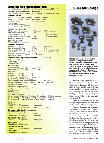
Metalformers have a wide variety of hydraulic clamps from which to choose, including ledge clamps (top), which can be placed manually in T-slots or bolted to the bolster or slide, and clamp directly on a flat clamping surface; and rod clamps (bottom), which mount in T-slots on the bolster or slide and U-slot cutouts on the clamping surface.
• Roto-Escam clamps hide beneath the press bed or inside the slide. The clamping rods rotate 90 deg. and retract below the bolster and slide plate, completely escaping the die area and allowing for clear access when loading and unloading a die. They can clamp in a T-slot or in a special machined hole.
• Swing clamps release the die by tilting 30 deg. to one side, and must have U-slot cutouts in the clamping surface.
• Traveling clamps use a driven chain mechanism or an air cylinder to auto- matically travel down a T-slot to reach the clamping surface.
A final suggestion: For any QDC hardware you purchase now, try to visu- alize how it might affect the future use of your basic pressroom equipment. For instance, consider any plans to add periph- eral equipment such as transfer systems, feed lines and conveyors when deciding what type of QDC hardware to buy and how and where to install it. MF
METALFORMING / JUNE 2010 23
Die lifters:
Select extension type:
Quote Recommend Hydraulic Mechanical
Not Required Rollers
Balls
Die support rails (bolster extensions):
Select bolster extension type:
Quote Recommend Removable Pivoting
Clamping for the bolster:
Quote Recommend Clamp Type:
Fixed Position Removable Clamping for the ram:
Quote Recommend Clamp Type:
Fixed Position Removable www.metalformingmagazine.com
Not Required Drop Down
Not Required
Not Required
_______ Lower _______ Lower
