
Page 27 - MetalForming April 2009
P. 27
tonnage is de-rated. Under these con- ditions, mechanical presses invite dam- age due to large shock loads. Double- action presses employ an outer slide capable of generating the forces needed to set draw beads near bottom dead center, taking advantage of full-ton- nage availability and low slide velocity. This minimizes shock loads to the die and press, and shock loads here will less likely exceed the rated capacity of the press.
General die design considerations for draw forming:
• Design small replaceable sections in high wear areas.
• Consider die coatings for high wear areas.
Draw Bead Types
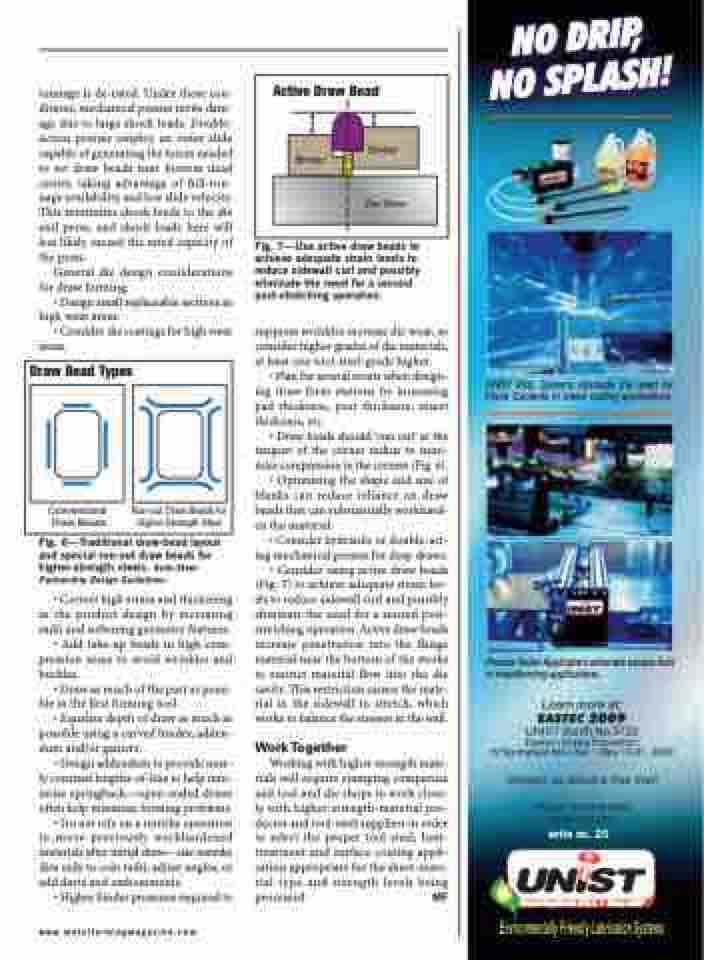
Active Draw Bead
Conventional Draw Beads
Run-out Draw Beads for Higher-Strength Steel
Fig. 7—Use active draw beads to achieve adequate strain levels to reduce sidewall curl and possibly eliminate the need for a second post-stretching operation.
suppress wrinkles increase die wear, so consider higher grades of die materials, at least one tool-steel-grade higher.
• Plan for several recuts when design- ing draw-form stations by increasing pad thickness, post thickness, insert thickness, etc.
• Draw beads should ‘run out’ at the tangent of the corner radius to mini- mize compression in the corners (Fig. 6).
• Optimizing the shape and size of blanks can reduce reliance on draw beads that can substantially workhard- en the material.
• Consider hydraulic or double-act- ing mechanical presses for deep draws. • Consider using active draw beads (Fig. 7) to achieve adequate strain lev- els to reduce sidewall curl and possibly eliminate the need for a second post- stretching operation. Active draw beads increase penetration into the flange material near the bottom of the stroke to restrict material flow into the die cavity. This restriction causes the mate- rial in the sidewall to stretch, which works to balance the stresses in the wall.
Work Together
Working with higher-strength mate- rials will require stamping companies and tool and die shops to work close- ly with higher-strength-material pro- ducers and tool-steel suppliers in order to select the proper tool steel, heat- treatment and surface-coating appli- cation appropriate for the sheet-mate- rial type and strength levels being processed. MF
Fig. 6—Traditional draw-bead layout and special run-out draw beads for higher-strength steels. Auto-Steel Partnership Design Guidelines.
• Correct high strain and thickening in the product design by increasing radii and softening geometry features.
• Add take-up beads in high-com- pression areas to avoid wrinkles and buckles.
• Draw as much of the part as possi- ble in the first forming tool.
• Equalize depth of draw as much as possible using a curved binder, adden- dum and/or gainers.
• Design addendum to provide near- ly constant lengths-of-line to help min- imize springback—open-ended draws often help minimize forming problems.
• Do not rely on a restrike operation to move previously workhardened materials after initial draw—use restrike dies only to coin radii, adjust angles, or add darts and embossments.
• Higher binder pressures required to
write no. 20
www.metalformingmagazine.com
Binder
Binder
Die Shoe
