
Page 35 - MetalForming December 2019
P. 35
Fabrication: Welding Well
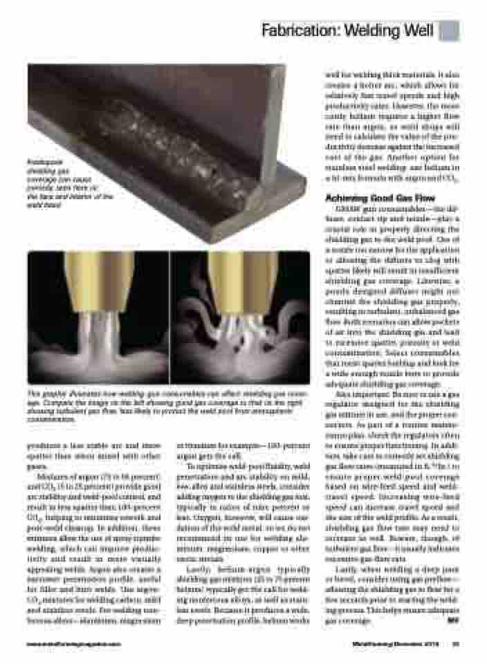
Inadequate
shielding gas
coverage can cause porosity, seen here on
the face and interior of the weld bead.
well for welding thick materials. It also creates a hotter arc, which allows for relatively fast travel speeds and high productivity rates. However, the more costly helium requires a higher flow rate than argon, so weld shops will need to calculate the value of the pro- ductivity increase against the increased cost of the gas. Another option for stainless steel welding: use helium in a tri-mix formula with argon and CO2.
Achieving Good Gas Flow
GMAW gun consumables—the dif- fuser, contact tip and nozzle—play a crucial role in properly directing the shielding gas to the weld pool. Use of a nozzle too narrow for the application or allowing the diffuser to clog with spatter likely will result in insufficient shielding gas coverage. Likewise, a poorly designed diffuser might not channel the shielding gas properly, resulting in turbulent, unbalanced gas flow. Both scenarios can allow pockets of air into the shielding gas and lead to excessive spatter, porosity or weld contamination. Select consumables that resist spatter buildup and look for a wide enough nozzle bore to provide adequate shielding gas coverage.
Also important: Be sure to use a gas regulator designed for the shielding gas mixture in use, and the proper con- nectors. As part of a routine mainte- nance plan, check the regulators often to ensure proper functioning. In addi- tion, take care to correctly set shielding gas flow rates (measured in ft.3/hr.) to ensure proper weld-pool coverage based on wire-feed speed and weld- travel speed. Increasing wire-feed speed can increase travel speed and the size of the weld profile. As a result, shielding gas flow rate may need to increase as well. Beware, though, of turbulent gas flow—it usually indicates excessive gas-flow rate.
Lastly, when welding a deep joint or bevel, consider using gas preflow— allowing the shielding gas to flow for a few seconds prior to starting the weld- ing process. This helps ensure adequate gas coverage. MF
This graphic illustrates how welding-gun consumables can affect shielding gas cover- age. Compare the image on the left showing good gas coverage to that on the right showing turbulent gas flow, less likely to protect the weld pool from atmospheric contamination.
produces a less stable arc and more spatter than when mixed with other gases.
Mixtures of argon (75 to 95 percent) and CO2 (5 to 25 percent) provide good arc stability and weld-pool control, and result in less spatter than 100-percent CO2, helping to minimize rework and post-weld cleanup. In addition, these mixtures allow the use of spray-transfer welding, which can improve produc- tivity and result in more visually appealing welds. Argon also creates a narrower penetration profile, useful for fillet and butt welds. Use argon- CO2 mixtures for welding carbon, mild and stainless steels. For welding non- ferrous alloys—aluminum, magnesium
or titanium for example—100-percent argon gets the call.
To optimize weld-pool fluidity, weld penetration and arc stability on mild, low-alloy and stainless steels, consider adding oxygen to the shielding gas mix, typically in ratios of nine percent or less. Oxygen, however, will cause oxi- dation of the weld metal, so we do not recommend its use for welding alu- minum, magnesium, copper or other exotic metals.
Lastly, helium-argon typically shielding-gas mixtures (25 to 75 percent helium) typically get the call for weld- ing nonferrous alloys, as well as stain- less steels. Because it produces a wide, deep penetration profile, helium works
www.metalformingmagazine.com
MetalForming/December 2019 33
