
Page 20 - MetalForming-Nov-2018-issue
P. 20
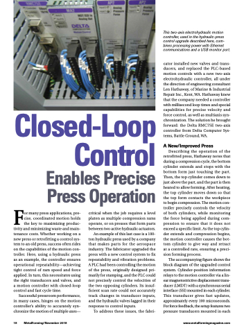
This two-axis electrohydraulic motion controller, used in the hydraulic-press control upgrade described here, com- bines processing power with Ethernet communications and a USB monitor port.
cator installed new valves and trans- ducers, and replaced the PLC-based motion controls with a new two-axis electrohydraulic controller, all under the direction of engineering consultant Len Hathaway, of Marine & Industrial Repair Inc., Kent, WA. Hathaway knew that the company needed a controller with millisecond loop times and special capabilities for precise velocity and force control, as well as multiaxis syn- chronization. The solution he brought forward: the Delta RMC75E two-axis controller from Delta Computer Sys- tems, Battle Ground, WA.
Control
Enables Precise Press Operation
Closed-Loop
For many press applications, pre- cise, coordinated motion holds the key to maximizing produc- tivity and minimizing waste and main- tenance costs. Whether working on a new press or retrofitting a control sys- tem to an old press, success often rides on the capabilities of the motion con- troller. Here, using a hydraulic press as an example, the controller ensures operational repeatability—achieving tight control of ram speed and force applied. In turn, this necessitates using the right transducers and valves, and a motion controller with closed-loop control and fast cycle time.
Successful pressroom performance, in many cases, hinges on the motion controller’s ability to accurately syn- chronize the motion of multiple axes—
critical when the job requires a level platen as multiple compression rams operate, or on presses that form parts between two active hydraulic actuators.
An example of this last case is a 100- ton hydraulic press used by a company that makes parts for the aerospace industry. The fabricator upgraded the press with a new control system to fix repeatability and vibration problems. A PLC had been controlling the motion of the press, originally designed pri- marily for stamping, and the PLC could not precisely control the velocities of the two opposing cylinders. Its insuf- ficient scan rate could not accurately track changes in transducer inputs, and the hydraulic valves lagged in their response to control inputs.
To address these issues, the fabri-
A New/Improved Press
Describing the operation of the retrofitted press, Hathaway notes that during a compression cycle, the bottom cylinder extends and stops with the bottom form just touching the part. Then, the top cylinder comes down to just above the part, and the part is then heated to allow forming. After heating, the top cylinder moves down so that the top form contacts the workpiece to begin compression. The motion con- troller precisely controls the velocity of both cylinders, while monitoring the force being applied during com- pression to ensure that it does not exceed a specific limit. As the top cylin- der extends and compression begins, the motion controller causes the bot- tom cylinder to give way and retract at a controlled rate, ensuring a preci- sion forming process.
The accompanying figure shows the block diagram of the upgraded control system. Cylinder-position information relays to the motion controller via a lin- ear magnetostrictive displacement trans- ducer (LMDT) with a synchronous serial interface (SSI) mounted in each cylinder. This transducer gives fast updates, approximately every 100 microseconds. For force feedback, the setup features two pressure transducers mounted in each
18 MetalForming/November 2018
www.metalformingmagazine.com
