
Page 42 - MetalForming-Jun-2018-issue
P. 42
Welding Well
By Tom Snow
Part-Design Considerations
for Spot and Projection Welding
Since resistance welding represents a great value-added opportunity for metalformers, it’s important to understand that proper part design plays a critical role. Although some tra- ditionally arc-welded parts can success- fully be resistance welded using com- mon processes such as spot, projection, seam, butt and flash welding, we rec- ommend that stampers design parts for resistance welding from the start, using the following tips, to help ensure an optimized welding process.
Flange Width
Spot welding stamped sheetmetal parts may appear simple and straight- forward, but inadequate flange width can cause quality problems. Design flanges wide enough to ensure easy access by the electrodes, while at the same time allowing enough distance from the edge to contain the weld heat. While sparks make for dramatic photos, expulsion of molten metal indicates compromised weld shear strength.
Refer to recommended edge-dis- tance specs, readily available to design- ers, which vary with sheet thickness. For example, to weld 18-gauge (0.050- in.-thick) low-carbon steel, the specs call for a minimum overlap of 9⁄16 in.
To overcome insufficient flange
Tom Snow is CEO of T. J. Snow Co., Chattanooga, TN, a supplier of resist- ance-welding machines, supplies, service and training. Snow, the imme- diate past chairman of the Resistance Welding Manufacturing Alliance, a standing committee of the American Welding
Society, shares his resistance-welding insights in MetalForming magazine’s Welding Well column every-other month.
Tom Snow, CEO
T. J. Snow Co. tomsnow@tjsnow.com
Use a double-bend offset spot-welding tip with an off- set nose for reaching into tight weld locations.
or angled electrode holder, which will save money in the long run because it enables use of standard straight tips.
Weld Spacing and Projection Welding
Another critical design specification: center-to- center spot-weld spacing. Since electricity always takes the path of least resistance, a second spot weld made too closely to the first will be weak, because part of the weld current shunts through the existing weld. Looking again at the example above (welding 18-gauge mild steel), specs call for a min-
width, metalformers can opt for weld- ing electrodes with an offset nose when welding near the edge. Double-bend offset electrodes also provide access to tight weld areas. However, these electrodes exhibit limited weld-force capacity and are expensive. As an alter- native, consider investing in an offset
imum weld spacing of 7⁄8 in.
Where the design calls for tighter
weld spacing, consider using projection welding. This resistance-welding process employs projections formed onto one of the parts. The projections, which can have single or multiple embosses of various shapes, concen-
40 MetalForming/June 2018
www.metalformingmagazine.com
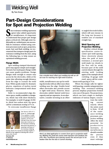
Here’s an ideal application to convert from spot to projection weld- ing. Welding the small tab causes weld expulsion and weakens the joint. Also, insufficient spot spacing causes the second spot to be weaker than the first due to current shunting.
trate the weld- ing current exactly where the joints need to form. Of all of the resist- ance-welding processes, pro- jection welding offers the most potential for productivity increases, so metalformers should consider the process even if they must redesign
