
Page 30 - MetalForming-Mar-2018-issue
P. 30
Fabrication: Shearing Defects
A
F
E
B
C
G
D
stresses and geometry. These natural effects, if not corrected and compen- sated for, become defects in the final product, reducing their quality.
Variables in the Shearing Process
Cutting angle (C in Fig. 1) represents the angle of the blade’s cutting edge. It influences the shearing force: Using two square-edged blades requires a higher cutting force than if the upper blade is ground at a slight angle, usually to a maximum of 87 deg. The lower blade always sits at 90 deg.
Fabricators often use four-edged blades (90-deg. blades), which allows them to turn the blades, and use all four edges for shearing. Angled blades, called two-edge blades, allow use of only two cutting edges—the opposite edges have an angle greater than 90 deg. and there- fore cannot be used for shearing.
Shearing angle (M, Fig. 2), less than 3 deg., has a great effect on shearing force and an important effect on twist- ing, which can occur when shearing thin strips.
Blade clearance, a key factor in ensuring good edge quality, represents the perpendicular distance (B in Fig. 1) between the shearing blades. The exact cutting clearance depends on work- piece thickness and material strength. Insufficient cutting clearance leads to increased tool wear and tooling costs, and cutting force will rise. Excessive cutting clearance causes the workpiece material to draw between the two blades—the cut edge will exhibit increased taper and excessive plastic deformation.
As a rule of thumb, for shearing mild steel to 10 mm thick, set blade clear- ance to 0.06 mm per mm of workpiece- material thickness. For work thicker than 10 mm, set blade clearance to 0.04 mm per mm of plate thickness. In Imperial units, set blade clearance to 0.06 in. per each in. of material to 1 in. thick, and to 0.04 in. per in. of plate thickness for work thicker than 1 in.
For example, to cut 16-mm-thick plate, set blade clearance to 0.64 mm
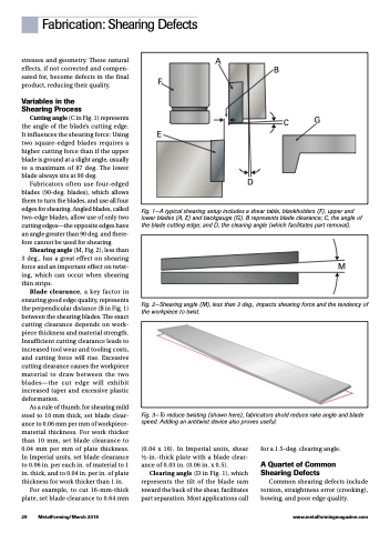
Fig. 1—A typical shearing setup includes a shear table, blankholders (F), upper and lower blades (A, E) and backgauge (G). B represents blade clearance; C, the angle of the blade cutting edge; and D, the clearing angle (which facilitates part removal).
Fig. 2—Shearing angle (M), less than 3 deg., impacts shearing force and the tendency of the workpiece to twist.
Fig. 3—To reduce twisting (shown here), fabricators shold reduce rake angle and blade speed. Adding an antitwist device also proves useful.
M
28 MetalForming/March 2018
www.metalformingmagazine.com
(0.04 x 16). In Imperial units, shear 1⁄2-in.-thick plate with a blade clear- ance of 0.03 in. (0.06 in. x 0.5).
Clearing angle (D in Fig. 1), which represents the tilt of the blade ram toward the back of the shear, facilitates part separation. Most applications call
for a 1.5-deg. clearing angle.
A Quartet of Common Shearing Defects
Common shearing defects include torsion, straightness error (crooking), bowing, and poor edge quality.
