
Page 32 - MetalForming-Mar-2018-issue
P. 32
Fabrication: Shearing Defects
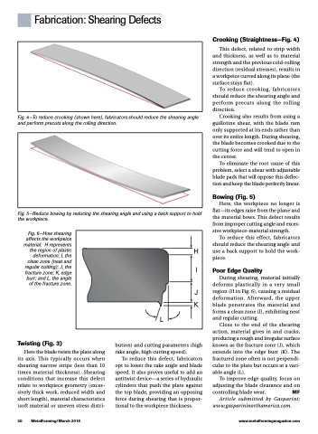
Fig. 4—To reduce crooking (shown here), fabricators should reduce the shearing angle and perform precuts along the rolling direction.
Fig. 5—Reduce bowing by reducing the shearing angle and using a back support to hold the workpiece.
Crooking (Straightness—Fig. 4)
This defect, related to strip width and thickness, as well as to material strength and the previous cold-rolling direction (residual stresses), results in a workpeice curved along its plane (the surface stays flat).
To reduce crooking, fabricators should reduce the shearing angle and perform precuts along the rolling direction.
Crooking also results from using a guillotine shear, with the blade ram only supported at its ends rather than over its entire length. During shearing, the blade becomes crooked due to the cutting force and will tend to open in the center.
To eliminate the root cause of this problem, select a shear with adjustable blade pads that will oppose this deflec- tion and keep the blade perfectly linear.
Bowing (Fig. 5)
Here, the workpiece no longer is flat—its edges raise from the plane and the material bows. This defect results from improper cutting angle and exces- sive workpiece-material strength.
To reduce this effect, fabricators should reduce the shearing angle and use a back support to hold the work- piece.
Poor Edge Quality
During shearing, material initially deforms plastically in a very small region (H in Fig. 6), causing a residual deformation. Afterward, the upper blade penetrates the material and forms a clean zone (I), exhibiting neat and regular cutting.
Close to the end of the shearing action, material gives in and cracks, producing a rough and irregular surface known as the fracture zone (J), which extends into the edge burr (K). The fractured zone often is not perpendi- cular to the plate but occurs at a vari- able angle (L).
To improve edge quality, focus on adjusting the blade clearance and on controlling blade wear. MF
Article submitted by Gasparini; www.gasparininorthamerica.com.
H I
J K
L
Fig. 6—How shearing affects the workpeice material: H represents the region of plastic deformation; I, the clean zone (neat and regular cutting); J, the fracture zone; K, edge burr; and L, the angle of the fracture zone.
Twisting (Fig. 3)
Here the blade twists the plate along its axis. This typically occurs when shearing narrow strips (less than 10 times material thickness). Shearing conditions that increase this defect relate to workpiece geometry (exces- sively thick work, reduced width and short length), material characteristics (soft material or uneven stress distri-
bution) and cutting parameters (high rake angle, high cutting speed).
To reduce this defect, fabricators opt to lower the rake angle and blade speed. It also proves useful to add an antitwist device—a series of hydraulic cylinders that push the plate against the top blade, providing an opposing force during shearing that is propor- tional to the workpiece thickness.
30 MetalForming/March 2018
www.metalformingmagazine.com
