
Page 42 - MetalForming-Jan-2018-issue
P. 42
Fabrication: DFM
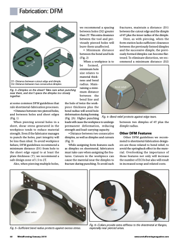
D1–Distance between cutout edge and dimple D2–Distance between two consecutive dimples
Fig. 3—Dimples on the sheet? Take care when punching near them, and don’t space the dimples too closely together.
at some common DFM guidelines that rule sheetmetal-fabrication processes. • Distance between two pierced holes, and between holes and sheet edges
(Fig. 1)
When piercing several holes in a
sheet, shear stress generated in the workpiece tends to reduce material strength. Even if the fabricator manages to punch the holes, part integrity will be less than ideal. To avoid workpiece failure, DFM guidelines recommend a minimum distance (D1) from hole to the sheet edge equal to at least the plate thickness ( T ); we recommend a safe design zone of 1.5 to 2T.
Also, when piercing multiple holes,
the hole of twice the work-
piece thickness plus the
bend radius will avoid hole deformation during forming
(Fig. 2A). Higher punching
loads will cause the workpiece to undergo permanent deformation, reducing strength and load-carrying capacity.
• Distance between two consecutive dimples, as well as dimples and cutouts (Fig. 3)
While assigning form features such as dimples on sheetmetal, fabricators must take care when assigning the fea- tures. Cutouts in the workpiece can cause the material near the dimples to fracture during punching. To avoid such
we recommend a spacing between holes (D2) greater than 2T. This extra clearance between the tool and pre- viously pierced holes will leave them unaffected.
• Minimum distance between the bend and hole (Fig. 2)
When a workpiece is to be formed,
minimum hole
size relates to
material thick- ness and bend radius. Main- taining a mini- mum distance between the bend line and
fractures, maintain a distance (D1) between the cutout edge and the dimple of 4T plus the inner radius of the dimple.
Here, as with piercing, when the form station lacks sufficient clearance between the previously formed dimples and the successive dimple, the previ- ously formed dimples can become flat- tened. To eliminate distortion, we rec- ommend a minimum distance (D2)
Fig. 4—Bend relief protects against edge tears.
Fig. 6—Collars provide extra stiffness to the sheetmetal at flanges, Fig. 5—Sufficient bend radius protects against excess stress. especially near pierced areas.
40 MetalForming/January 2018
www.metalformingmagazine.com
between two dimples of 4T plus the dimple radius.
Other DFM Features
Other DFM guidelines we recom- mend to sheetmetal-fabrication design- ers are those related to bend relief, to avoid the springback effect in the mate- rial. Overlooking the importance of these features not only will increase the number of ECOs but also will result in increased scrap and related costs.
