
Page 23 - MetalForming September 2017
P. 23
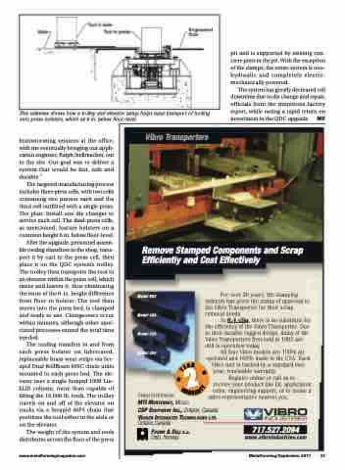
                 This sideview shows how a trolley and elevator setup helps ease transport of tooling onto press bolsters, which sit 6 in. below floor-level.
brainstorming sessions at the office, with me eventually bringing our appli- cation engineer, Ralph Stellmacher, out to the site. Our goal was to deliver a system that would be fast, safe and durable.”
The targeted manufacturing process includes three press cells, with two cells containing two presses each and the third cell outfitted with a single press. The plan: Install one die changer to service each cell. The dual-press cells, as mentioned, feature bolsters on a common height 6 in. below floor-level.
After the upgrade, personnel assem- ble tooling elsewhere in the shop, trans- port it by cart to the press cell, then place it on the QDC system’s trolley. The trolley then transports the tool to an elevator within the press cell, which raises and lowers it, thus eliminating the issue of the 6-in. height difference from floor to bolster. The tool then moves into the press bed, is clamped and ready to use. Changeovers occur within minutes, although other asso- ciated processes extend the total time needed.
The tooling transfers to and from each press bolster on lubricated, replaceable brass wear strips via Ser- apid Dual RollBeam 60SC chain units mounted to each press bed. The ele- vator uses a single Serapid 100R Lin- kLift column, more than capable of lifting the 16,000-lb. tools. The trolley travels on and off of the elevator on tracks via a Serapid 40PS chain that positions the tool either in the aisle or on the elevator.
The weight of the system and tools distributes across the floor of the press
pit and is supported by existing con- crete piers in the pit. With the exception of the clamps, the entire system is non- hydraulic and completely electro- mechanically powered.
The system has greatly decreased cell downtime due to die change and repair, officials from the munitions factory report, while noting a rapid return on
investment in the QDC upgrade.
M F
     Vibro Transporters
Remove Stamped Components and Scrap Efficiently and Cost Effectively
Model 850
Model 450
Model 320
Model 250
Global Distribution
For over 30 years, the stamping industry has given the stamp of approval to the Vibro Transporter for their scrap removal needs.
At 0.4 cfm, there is no substitute for the efficiency of the Vibro Transporter. Due to their durable rugged design, many of the Vibro Transporters first sold in 1985 are still in operation today.
All four Vibro models are 100% air operated and 100% made in the USA. Each
Vibro unit is backed by a standard two- year, renewable warranty.
Register online or call us to receive your product line kit, application video, engineering support, or to locate a
sales representative nearest you.
    MTI MONTERREY, MEXICO
CSP EQUIPMENT INC., Ontario, Canada
VEUGEN INTEGRATED TECHNOLOGIES LTD.
Ontario,Canada
FOSMO & DELI A.S.
Oslo, Norway
717.527.2094
                            www.vibroindustries.com
www.metalformingmagazine.com
MetalForming/September 2017
21
2
A
E
Y
R
R
Y
T
A
N
W
A
R
