
Page 48 - MetalForming August 2017
P. 48
Tooling by Design
By Peter Ulintz
Punching Technology—Force Limitations
Calculating punching force and punch-tip pressure is straightforward. To calculate the force required to create a punched hole (F ):
Fp = (L)(t)()
Where:
L = punch-tip circumference or profile length
t = sheetmetal thickness
= workpiece-material shear strength
Note that metalformers may find it difficult to acquire
accurate shear-strength data, and to duplicate test results. Consequently, they often will use assumptions in force cal- culations rather than use actual test data. For example, engi- neers may assume that the shear strength of mild steel equals 70 to 80 percent of its ultimate tensile strength (UTS); for aluminum, they might assume shear strength to be 50 percent of UTS; and for stainless steel, 90 percent of UTS.
However, shear strength can vary significantly within the same material type. For example, shear strength for copper alloys can range from 50 to 90 percent of UTS, depending on the alloy. As a result, calculating accurate cutting and punching forces can prove challenging, due to the lack of reliable and accurate shear data.
To simplify matters, engineers can substitute UTS for shear strength in their cutting- and punch-force calculations, but the result will be an overestimate of actual forces.
With punching force (Fp) calculated, we can derive punch- tip pressure (Pt). For a standard shoulder punch:
Pt = Fp / [()(1⁄2d)2]
Where:
d = the cross-sectional area of the punch tip
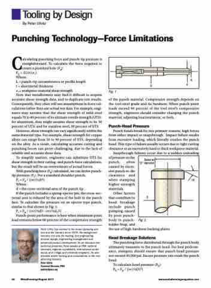
If the punch includes a spring-ejector pin, the cross-sec-
tional area is reduced by the area of the hole in the punch face. To calculate the pressure on an ejector-type punch, similar to that shown in Fig. 1:
Pt = Fp / [()(1⁄2d)2 -()(1⁄2d1)2]
Punch-point performance is best when maximum point load remains below 60 percent of the compressive strength
Peter Ulintz has worked in the metal stamping and tool and die industry since 1978. His background includes tool and die making, tool engineering, process design, engineering management and advanced product development. As an educator and technical presenter, Peter speaks at PMA national seminars, regional roundtables, international confer- ences, and college and university programs. He also provides onsite training and consultations to the met- alforming industry.
Peter Ulintz
Technical Director, PMA pulintz@pma.org
D
d1 d
p
Fig. 1
of the punch material. Compressive strength depends on the tool-steel grade and its hardness. When punch-point loads exceed 60 percent of the tool steel’s compressive strength, engineers should consider changing the punch material, adjusting heattreatment, or both.
Punch-Head Pressure
Punch heads break for two primary reasons: high forces from either impact or snapthrough. Impact failure results from excessive loading, which literally crushes the punch head. This type of failure usually occurs due to tight cutting clearance or an excessively hard or thick workpiece material.
Snapthrough failures occur due to a sudden unloading of pressure on the
punch, often
caused by exces-
sive punch-to-die clearance and when stamping higher-strength materials.
Same as “D” diameter
D
10˚
Other factors
that contribute to
head breakage
include punch
pumping, caused
by poor punch-
body to punch-
holder fitup, and
the use of high-hardness backing plates.
Head Breakage Solutions
The punching force distributed through the punch body ultimately transmits to the punch head. For best perform- ance, stampers should ensure that punch-head pressure not exceed 40,000 psi. Excess pressure can crush the punch head.
To calculate head pressure (Ph): Ph = Fp / [()(1⁄2D)2]
Fig. 2
46 MetalForming/August 2017
www.metalformingmagazine.com
