
Page 40 - MetalForming June 2017
P. 40
Tooling by Design
By Peter Ulintz
Higher Strength Requires Higher Levels of Knowledge
The use of advanced high- strength steel (AHSS) with ulti- mate tensile strengths of approx- imately 145 ksi is fairly common in the automotive industry. Trends indicate growth in applications requiring even higher-strength grades, to 200 ksi and beyond. These ultrahigh-strength materials dramatically affect how we process tooling, select press equipment and view the overall stamping process.
AHSS materials often are referred to as automotive materials, and right- fully so, as this is the application for which they were developed and first used. However, it would be unwise for metalformers not involved with auto- motive components to ignore what is happening in the world of AHSS mate- rials. In the 1970s, high-strength low- alloy (HSLA) steels were considered to be automotive grades. However, these materials now find use in nearly every industry due to their higher strength, good formability and ease of weldabil- ity. The same likely will hold true for some AHSS workhorse grades, dual- phase grades in particular.
In general, metalformers processing these higher-strength materials must have a higher level of understanding
Peter Ulintz has worked in the metal stamping and tool and die industry since 1978. His back- ground includes tool and die making, tool engi- neering, process design, engineering manage- ment and advanced product development. As an educator and technical
presenter, Peter speaks at PMA national seminars, regional roundtables, international conferences, and college and university programs. He also pro- vides onsite training and consultations to the met- alforming industry.
Peter Ulintz
Technical Director, PMA pulintz@pma.org
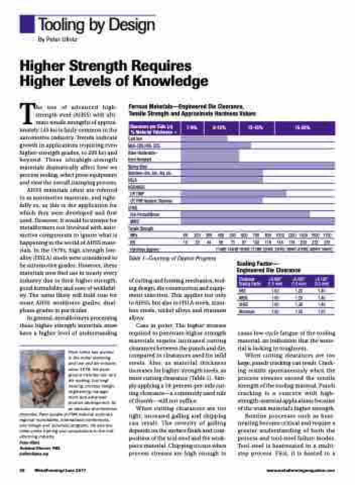
Ferrous Materials—Engineered Die Clearance, Tensile Strength and Approximate Hardness Values
Clearance per Side (Δ) % Material Thickness→
Cast Iron
Mild–CRS,HRS, CDS Bake-Hardenable– Dent-Resistant
Spring Steel
Stainless–2xx, 3xx, 4xx, etc. HSLA
HSS/AHSS
DP, TWIP
CP, TRIP, Austenic Stainless UHSS
Hot-Formed/Boron
MART
Tensile Strength
MPa
KSI
Hardness (approx.)
69 200 300 400 500 600 700 800 1000 1200 1400 1600 1750 10 29 44 58 73 87 102 116 145 174 203 232 255
114HB 144HB 183HB 213HB 22HRC 33HRC 38HRC 43HRC 48HRC 50HRC
Table 1—Courtesy of Dayton Progress
of cutting and forming mechanics, tool- ing design, die construction and equip- ment selection. This applies not only to AHSS, but also to HSLA steels, stain- less steels, nickel alloys and titanium alloys.
Case in point: The higher stresses required to penetrate higher-strength materials require increased cutting clearances between the punch and die, compared to clearances used for mild steels. Also, as material thickness increases for higher-strength steels, so must cutting clearance ( Table 1). Sim- ply applying a 10-percent-per-side cut- ting clearance—a commonly used rule of thumb—will not suffice.
When cutting clearances are too tight, increased galling and chipping can result. The severity of galling depends on the surface finish and com- position of the tool steel and the work- piece material. Chipping occurs when process stresses are high enough to
Scaling Factor— Engineered Die Clearance
HSS 1.00 1.20 1.40 AHSS 1.00 1.20 1.40 UHSS 1.00 1.30 1.40 Aluminum 1.00 1.03 1.05
cause low-cycle fatigue of the tooling material, an indication that the mate- rial is lacking in toughness.
When cutting clearances are too large, punch cracking can result. Crack- ing results spontaneously when the process stresses exceed the tensile strength of the tooling material. Punch cracking is a concern with high- strength-material applications because of the work material’s higher strength.
Routine processes such as heat- treating become critical and require a greater understanding of both the process and tool-steel failure modes. Tool steel is heattreated in a multi- step process. First, it is heated to a
7-9%
9-12%
12-15%
38 MetalForming/June 2017
www.metalformingmagazine.com
15-20%
Thickness <0.060" >0.060" >0.120"
Scaling Factor (1.5 mm) (1.5 mm) (3.0 mm)
